Recovery
Intro
The following documentation describes the process of recovering hardware from the brick state using an RTE and Dasharo open-source firmware.
Prerequisites
- Prepared RTE
- 6x female-female wire cables
Connections
To prepare the stand for flashing follow the steps described below:
- Open the platform cover.
-
Connect the 6-pin flash header to the SPI header on RTE.
SPI header 6 pin header Vcc pin 1 (Vcc) GND pin 2 (GND) CS pin 4 (CS) SCLK pin 6 (CLK) MISO pin 5 (MISO) MOSI pin 3 (MOSI) ______ > | | Vcc 3.3V ----1 2---- GND | | MOSI ----3 4---- CS | | MISO ----5 6---- CLK |______|
Firmware flashing
To flash firmware follow the steps described below:
- Login to RTE via
sshorminicom. - Turn on the platform by connecting the power supply.
- Wait at least 5 seconds.
- Turn off the platform by using the power button.
- Wait at least 3 seconds.
-
Set the proper state of the SPI by using the following commands on RTE:
# set SPI Vcc to 3.3V echo 1 > /sys/class/gpio/gpio405/value # SPI Vcc on echo 1 > /sys/class/gpio/gpio406/value # SPI lines ON echo 1 > /sys/class/gpio/gpio404/value -
Wait at least 2 seconds.
- Disconnect the power supply from the platform.
- Wait at least 2 seconds.
-
Flash the platform by using the following command:
flashrom -p linux_spi:dev=/dev/spidev1.0,spispeed=16000 -w [path_to_binary]Flashing with flashrom takes about 1 minute.
-
Change back the state of the SPI by using the following commands:
echo 0 > /sys/class/gpio/gpio404/value echo 0 > /sys/class/gpio/gpio406/value -
Turn on the platform by connecting the power supply.
The first boot of the platform after proceeding with the above procedure can take much longer than standard.
Connections
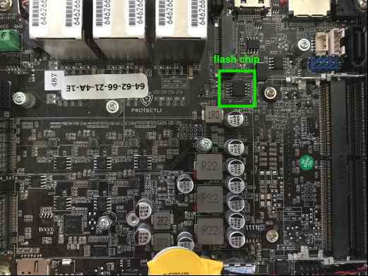
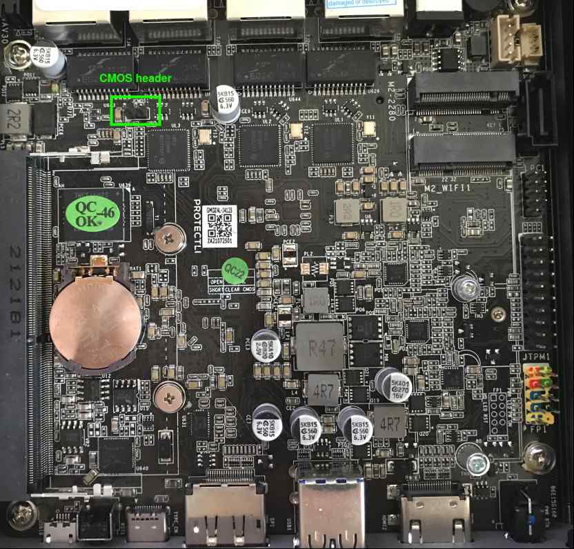
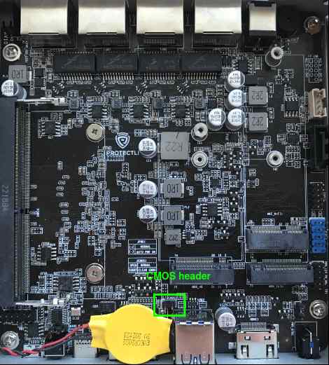
Set up the connections required for external flashing as described in Generic Testing Stand Setup. Protectli VP46XX are flashed using the Pomona clip connection variant. Use the pictures below to easily locate essential components on the mainboard.
SPI flash chip location
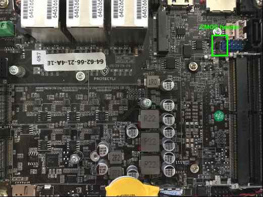
CMOS header location
Firmware flashing
To flash firmware, follow the steps described in Generic Testing Stand Setup , noting that: * The chip voltage for this platform is 3.3V * The proper flashrom parameters for this platform are:
```bash
flashrom -p linux_spi:dev=/dev/spidev1.0,spispeed=16000 -c "MX25L12835F/MX25L12845E/MX25L12865E" -w [path_to_binary]
```
Prerequisites
- Prepared RTE
- 6x female-female wire cables
Connections
To prepare the stand for flashing follow the steps described below:
- Open the platform cover.
-
Connect the J1 and J2 flash headers to the SPI header on RTE.
SPI header VP66XX J2 Vcc pin 1 (Vcc) SCLK pin 3 (CLK) MOSI pin 4 (MOSI) SPI header VP66XX J1 GND pin 4 (GND) CS pin 1 (CS) MISO pin 2 (MISO)
Firmware flashing
To flash firmware follow the steps described below:
- Login to RTE via
sshorminicom. - Turn on the platform by connecting the power supply.
- Wait at least 5 seconds.
- Turn off the platform by using the power button.
- Wait at least 3 seconds.
-
Set the proper state of the SPI by using the following commands on RTE:
# set SPI Vcc to 3.3V echo 1 > /sys/class/gpio/gpio405/value # SPI Vcc on echo 1 > /sys/class/gpio/gpio406/value # SPI lines ON echo 1 > /sys/class/gpio/gpio404/value -
Wait at least 2 seconds.
- Disconnect the power supply from the platform.
- Wait at least 2 seconds.
-
Flash the platform by using the following command:
flashrom -p linux_spi:dev=/dev/spidev1.0,spispeed=16000 -w [path_to_binary]Flashing with flashrom takes about 1 minute.
-
Change back the state of the SPI by using the following commands:
echo 0 > /sys/class/gpio/gpio404/value echo 0 > /sys/class/gpio/gpio406/value -
Reset the CMOS battery (short JCMOS1 header for a couple of seconds).
- Turn on the platform by connecting the power supply.
The first boot of the platform after proceeding with the above procedure can take much longer than standard.
Connections
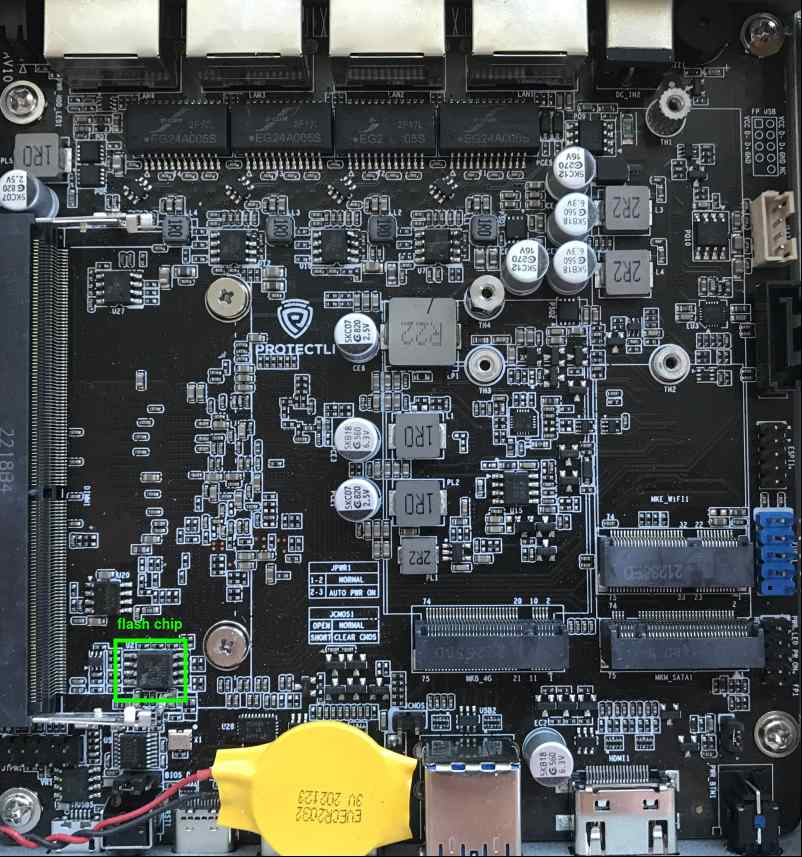
Set up the connections required for external flashing as described in Generic Testing Stand Setup Protectli VP2410 are flashed using the Pomona clip connection variant. Use the pictures below to easily locate essential components on the mainboard.
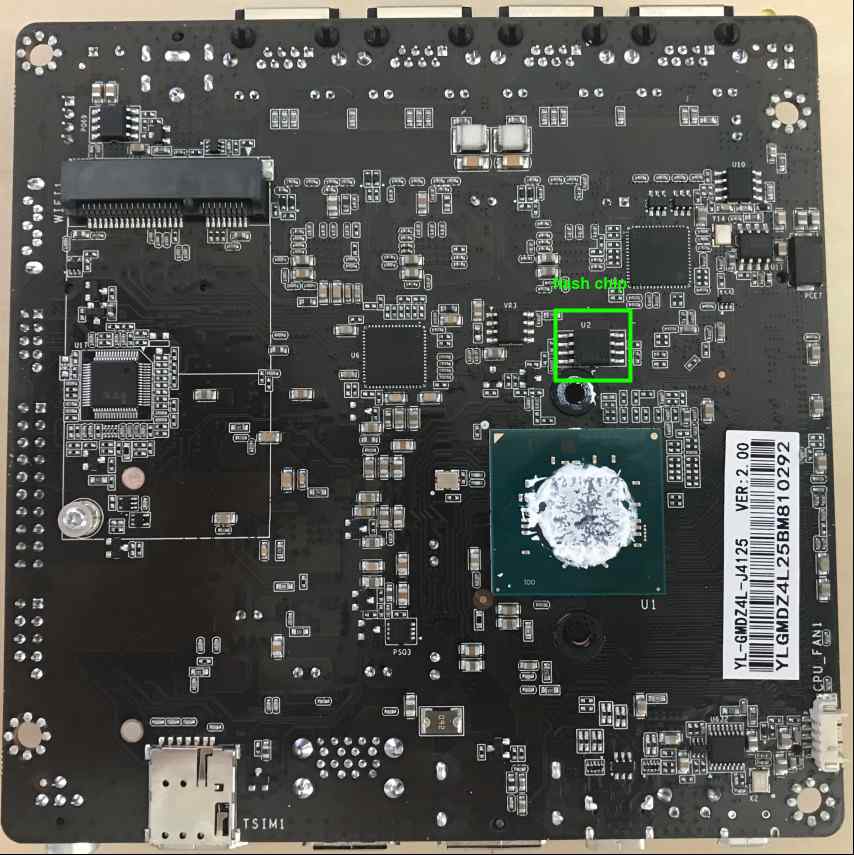
SPI flash chip location
Completely remove the motherboard from the platform cover.
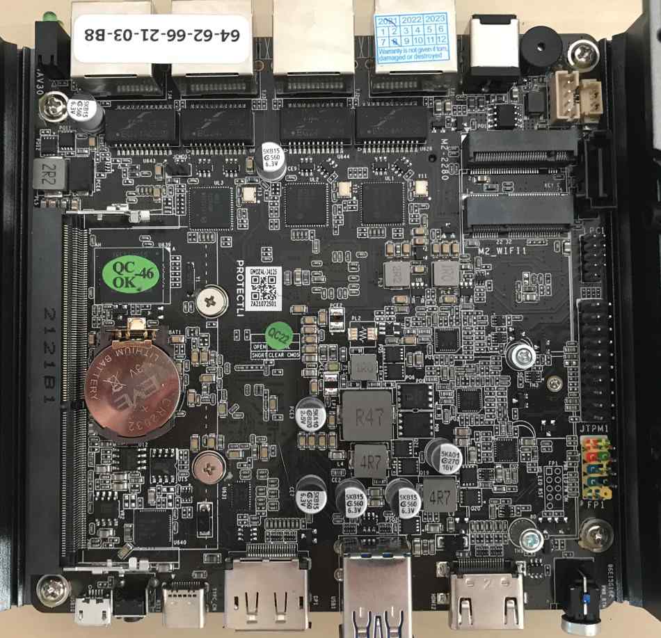
If there is little thermal paste on the CPU, apply it before reassembling the motherboard to the platform cover.
CMOS header location
Firmware flashing
To flash firmware, follow the steps described in Generic Testing Stand Setup , noting that: * The chip voltage for this platform is 1.8V * The proper flashrom parameters for this platform are:
```bash
flashrom -p linux_spi:dev=/dev/spidev1.0,spispeed=16000 -c "MX25U6435E/F" -w [path_to_binary]
```
Prerequisites
- Prepared RTE
- SOIC-8 Pomona clip
- 6x female-female wire cables
Connections
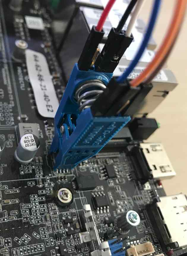
Set up the connections required for external flashing as described in Generic Testing Stand Setup. Protectli VP2420 are flashed using the Pomona clip connection variant. Use the pictures below to easily locate essential components on the mainboard.
SPI flash chip
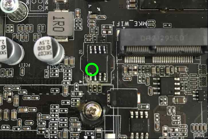
CMOS header
Firmware flashing
To flash firmware, follow the steps described in Generic Testing Stand Setup , noting that: * The chip voltage for this platform is 3.3V * The proper flashrom parameters for this platform are:
```bash
flashrom -p linux_spi:dev=/dev/spidev1.0,spispeed=16000 -c "MX25L12835F/MX25L12845E/MX25L12865E" -w [path_to_binary]
```
Prerequisites
- Prepared RTE
- 6x female-female wire cables
Connections
To prepare the stand for flashing follow the steps described below:
- Open the platform cover.
-
Connect the J1 and J2 flash headers to the SPI header on RTE.
SPI header VP2430 J2 Vcc pin 1 (Vcc) SCLK pin 3 (CLK) MOSI pin 4 (MOSI) SPI header VP2430 J1 GND pin 4 (GND) CS pin 1 (CS) MISO pin 2 (MISO)
Firmware flashing
To flash firmware follow the steps described below:
- Login to RTE via
sshorminicom. - Turn on the platform by connecting the power supply.
- Wait at least 5 seconds.
- Turn off the platform by using the power button.
- Wait at least 3 seconds.
-
Set the proper state of the SPI by using the following commands on RTE:
# set SPI Vcc to 3.3V echo 1 > /sys/class/gpio/gpio405/value # SPI Vcc on echo 1 > /sys/class/gpio/gpio406/value # SPI lines ON echo 1 > /sys/class/gpio/gpio404/value -
Wait at least 2 seconds.
- Disconnect the power supply from the platform.
- Wait at least 2 seconds.
-
Flash the platform by using the following command:
flashrom -p linux_spi:dev=/dev/spidev1.0,spispeed=16000 \
    -c "MX25L12833F/MX25L12835F/MX25L12845E/MX25L12865E/MX25L12873F" \
    -w [path_to_binary]
Flashing with flashrom takes about 1 minute.
-
Change back the state of the SPI by using the following commands:
echo 0 > /sys/class/gpio/gpio404/value echo 0 > /sys/class/gpio/gpio406/value -
Turn on the platform by connecting the power supply.
The first boot of the platform after proceeding with the above procedure can take much longer than standard.
Prerequisites
- Prepared RTE
- 6x female-female wire cables
Connections
To prepare the stand for flashing follow the steps described below:
- Open the platform cover.
-
Connect the J1 and J2 flash headers to the SPI header on RTE.
SPI header VP32XX J1 Vcc pin 1 (Vcc) SCLK pin 3 (CLK) MOSI pin 4 (MOSI) SPI header VP32XX J2 GND pin 4 (GND) CS pin 1 (CS) MISO pin 2 (MISO)
Firmware flashing
To flash firmware follow the steps described below:
- Login to RTE via
sshorminicom. - Turn on the platform by connecting the power supply.
- Wait at least 5 seconds.
- Turn off the platform by using the power button.
- Wait at least 3 seconds.
-
Set the proper state of the SPI by using the following commands on RTE:
# set SPI Vcc to 3.3V echo 1 > /sys/class/gpio/gpio405/value # SPI Vcc on echo 1 > /sys/class/gpio/gpio406/value # SPI lines ON echo 1 > /sys/class/gpio/gpio404/value -
Wait at least 2 seconds.
- Disconnect the power supply from the platform.
- Wait at least 2 seconds.
-
Flash the platform by using the following command:
flashrom -p linux_spi:dev=/dev/spidev1.0,spispeed=16000 -w [path_to_binary]Flashing with flashrom takes about 1 minute.
-
Change back the state of the SPI by using the following commands:
echo 0 > /sys/class/gpio/gpio404/value echo 0 > /sys/class/gpio/gpio406/value -
Reset the CMOS battery (short JCMOS header for a couple of seconds).
- Turn on the platform by connecting the power supply.
The first boot of the platform after proceeding with the above procedure can take much longer than standard.
Prerequisites
- Prepared RTE
- 6x female-female wire cables
Connections
To prepare the stand for flashing follow the steps described below:
- Open the platform cover.
-
Connect the J1 and J2 flash headers to the SPI header on RTE.
SPI header VP2440 J2 Vcc pin 1 (Vcc) SCLK pin 3 (CLK) MOSI pin 4 (MOSI) SPI header VP2440 J1 GND pin 4 (GND) CS pin 1 (CS) MISO pin 2 (MISO)
Firmware flashing
To flash firmware follow the steps described below:
- Login to RTE via
sshorminicom. - Turn on the platform by connecting the power supply.
- Wait at least 5 seconds.
- Turn off the platform by using the power button.
- Wait at least 3 seconds.
-
Set the proper state of the SPI by using the following commands on RTE:
# set SPI Vcc to 3.3V echo 1 > /sys/class/gpio/gpio405/value # SPI Vcc on echo 1 > /sys/class/gpio/gpio406/value # SPI lines ON echo 1 > /sys/class/gpio/gpio404/value -
Wait at least 2 seconds.
- Disconnect the power supply from the platform.
- Wait at least 2 seconds.
-
Flash the platform by using the following command:
flashrom -p linux_spi:dev=/dev/spidev1.0,spispeed=16000 \
    -c "MX25L12833F/MX25L12835F/MX25L12845E/MX25L12865E/MX25L12873F" \
    -w [path_to_binary]
Flashing with flashrom takes about 1 minute.
-
Change back the state of the SPI by using the following commands:
echo 0 > /sys/class/gpio/gpio404/value echo 0 > /sys/class/gpio/gpio406/value -
Turn on the platform by connecting the power supply.
The first boot of the platform after proceeding with the above procedure can take much longer than standard.