Sonoff preparation
The following page is based on the EPSHome and Tasmota documentations.
Firmware setup
Connecting the programmer
As for choosing the programming device, we have found that both ch341a in UART mode and a generic USB-UART adapter work seamlessly.
Please attach the programmer wires as specified in this step of Tasmota documentation.
-
Open the Sonoff case.
-
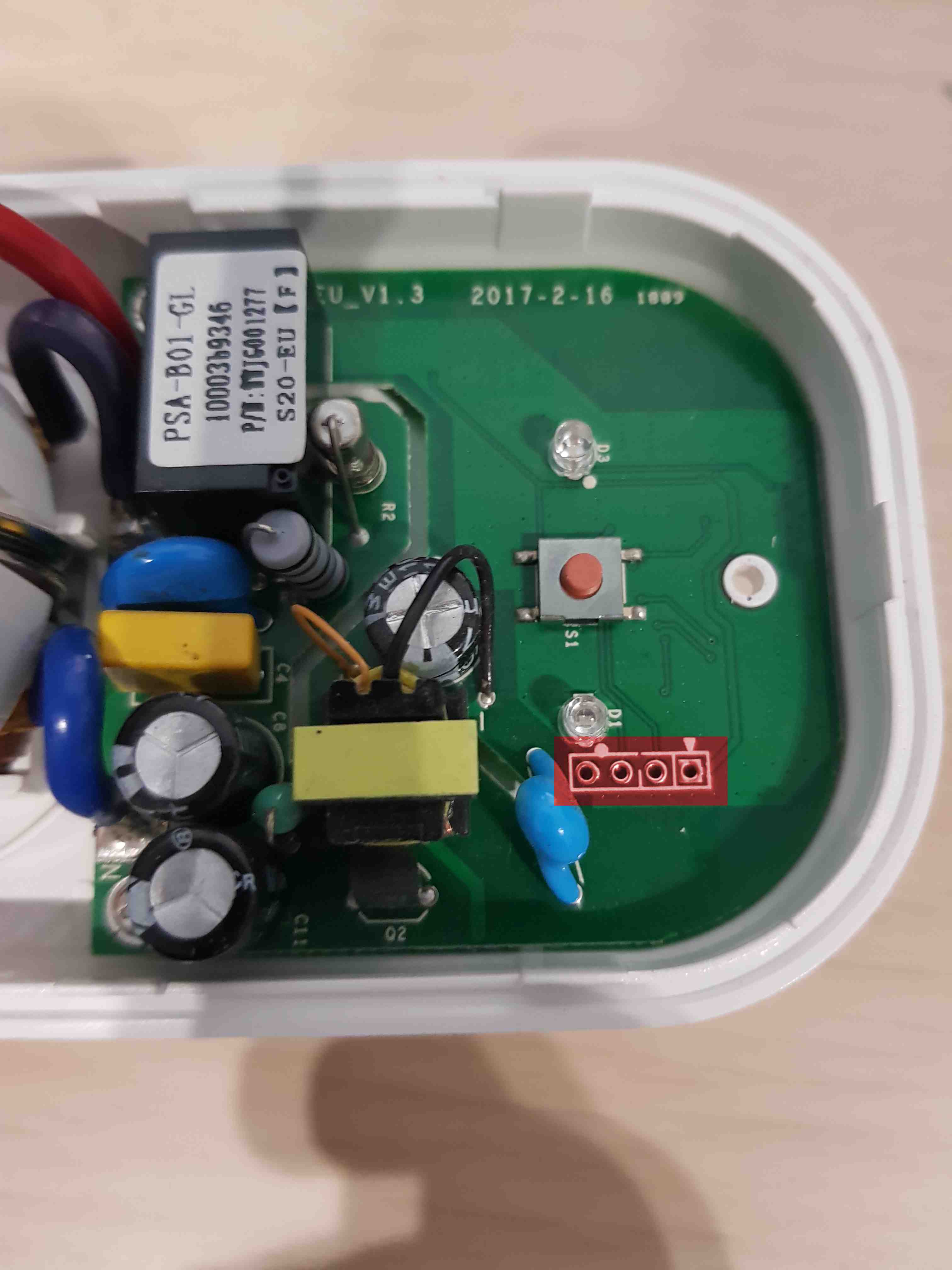
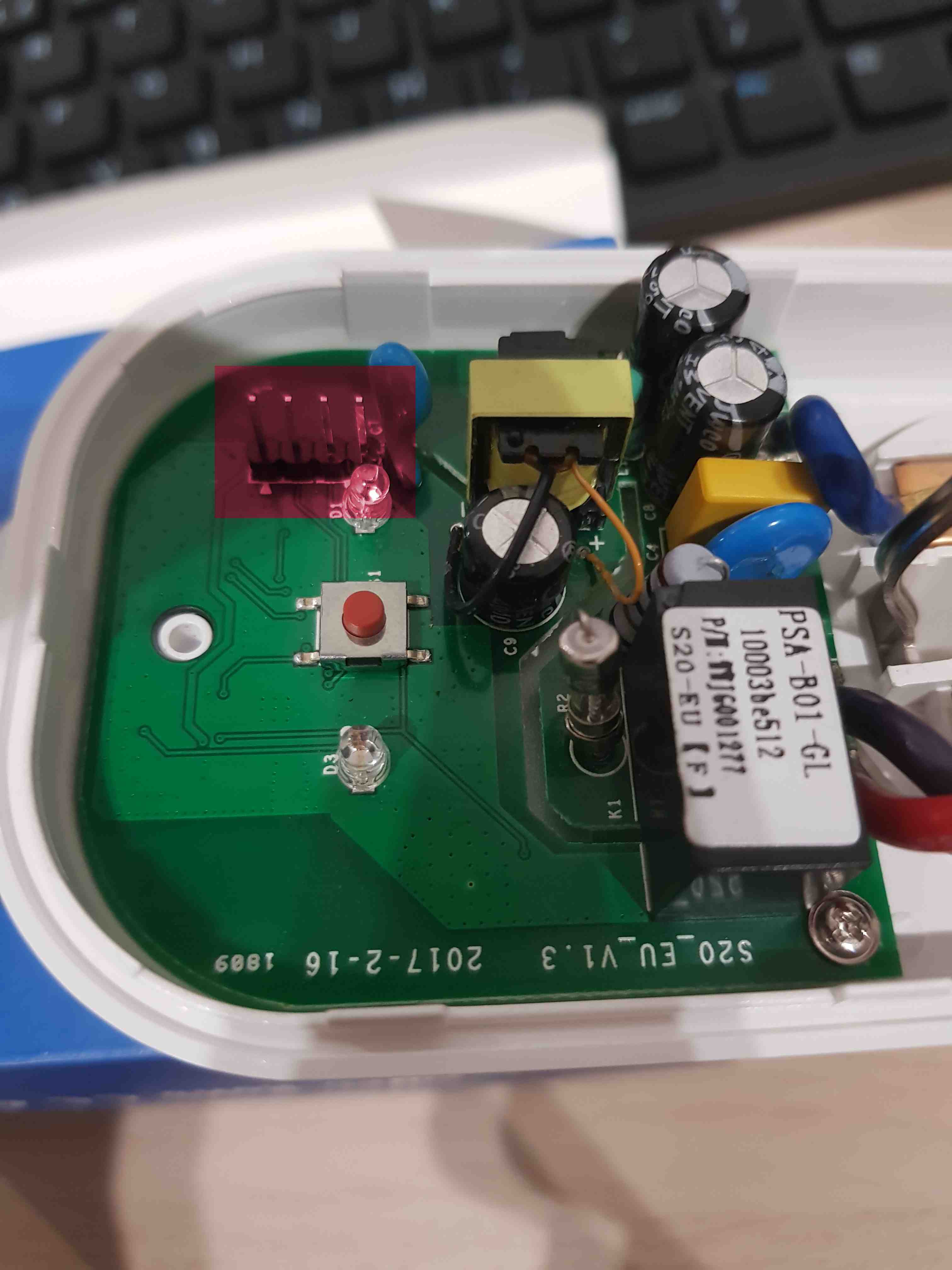
Check if the headers are soldered to the board. If not - 4 pin header raster 2.54 mm should be soldered to the board in accordance with the below images.
-
Connect the USB-UART converter to the USB port.
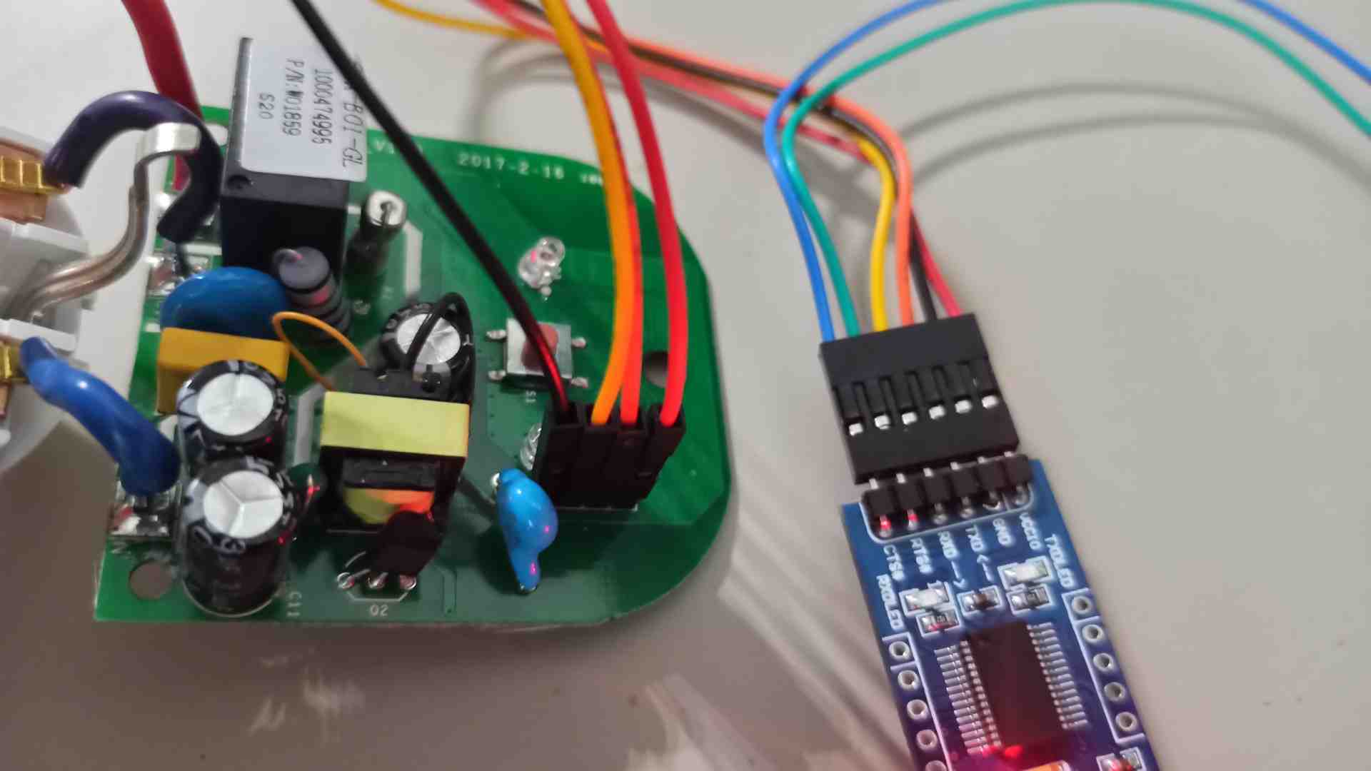
After connecting the wires, remember to plug in the programmer while holding down the Sonoff power button to get into flash mode:
- Disconnect the programmer from your PC
- Hold down the Sonoff power button
- Plug the programmer into the PC
- Release the power button
Installation and initial configuration of the firmware
We strongly advise using the more popular Tasmota, which has demonstrated higher stability in our office, over ESPhome. However, in case you have reasons to choose the latter, our guide provides instructions for both.
The most lightweight and versatile way to go about flashing Tasmota is using
esptool.py. You can install it for your copy of Python
by running
pip install esptool
-
Figure out what is the device name of the programmer - run
dmesg | tailand see what is the most recently attached/dev/ttyUSB, e.g./dev/ttyUSB0. -
Backup the vendor firmware by running
esptool.py --port /dev/ttyUSB0 read_flash 0x00000 0x100000 backup.binNote:
/dev/ttyUSB0is example device - check whetherUSB0is the correct one. -
Erase firmware
esptool.py --port /dev/ttyUSB0 erase_flash -
Download a copy of tasmota.bin and place it in your working directory
-
Flash Sonoff with
tasmota.binesptool.py write_flash -fm dout 0x0 tasmota.bin -
After the flashing has been completed, unplug the programmer from your PC and detach all wires from the Sonoff. Reassemble the Sonoff and plug it into a socket.
-
Connect to Sonoff's temporary WiFi hotspot named after Tasmota, visit
http://192.168.4.1/inand make a note of the MAC address to be able to assign an IP to the MAC address.Note: Use a normal browser so that when you log on to the new network, Sonoff shows which IP has been assigned. If you use the system pop-up with the Wi-Fi login page, it will close immediately after connecting to a new network and you will not see the new IP.
-
Visit
http://192.168.4.1and follow on-screen instructions to connect the Sonoff to your network of choice. -
The new IP address will be displayed and an attempt will be made to connect to it. Make a note of this IP and assign it to a MAC address.
-
Create a Sonoff configuration file. The file extension should be
.yamland it should contain the device configuration.Example configuration:
esphome: name: XXXXXX platform: ESP8266 board: esp01_1m wifi: ssid: "XXXXXX" password: "XXXXXX" # manual_ip: # # Set this to the IP of the ESP # static_ip: 192.168.4.187 # # Set this to the IP address of the router. Often ends with .1 # gateway: 192.168.4.1 # # The subnet of the network. 255.255.255.0 works for most home networks. # subnet: 255.255.255.0 power_save_mode: none # # Enable fallback hotspot (captive portal) in case wifi connection fails ap: ssid: "Sonoff1 Fallback Hotspot" password: "123456789" captive_portal: # Enable logging logger: # Enable Home Assistant API api: ota: binary_sensor: - platform: gpio pin: number: GPIO0 mode: INPUT_PULLUP inverted: True name: "Sonoff S20 Button" on_press: - switch.toggle: relay - platform: status name: "Sonoff S20 Status" switch: - platform: gpio name: "Sonoff S20 Relay" pin: GPIO12 id: relay output: - platform: esp8266_pwm id: s20_green_led pin: GPIO13 inverted: True light: - platform: monochromatic name: "Sonoff S20 Green LED" output: s20_green_led web_server: port: 80 reboot_timeout: 0s -
Run the docker container in the folder containing created
.yamlconfiguration file:docker run --rm -v "${PWD}":/config --device=/dev/ttyUSB0 -p 6052:6052 -it esphome/esphome -
Open the browser and type into the web browser the following address:
http://localhost:6052/ -
Put the device in flash mode. Putting the device in this mode should be done in accordance with the documentation.
-
Change the upload method from OTA to
/dev/ttyUSB0. After this operation, the new element with the name specified inesphome:nameshould be displayed. -
Select the option
Upload. After clicking, the program should generate the image, compile it and upload it to the device. -
After successful upload replug the device to the USB (without the button pressed) to get out of the flashing mode.
-
Open connection to the device in the PC terminal by typing:
sudo minicom -D /dev/ttyUSB0 -o -b 115200.Note:
/dev/ttyUSB0is example device - check whetherUSB0is the correct one. -
Check if the device is responsible - whether network connectivity information is generated.
Note: The effective range for this device is only a few meters.
-
Based on the minicom logs read the IP address assigned to the device.
-
The device should have a statically assigned IP address based on its MAC address - this will make it easy to find it on the network.
The device will host the website which can be used to switch the relay.
Bear in mind that the antenna in this device is very poorly performing - effective range is only few meters
Controlling the relay switch
To switch the relay the following bash commands may be used:
192.168.43.171should be replaced with assigned IP. Note: You can only connect to Sonoff via an unsecured connectionhttp://
curl -X POST http://192.168.43.171/cm?cmnd=Power%20TOGGLE
curl -X POST http://192.168.43.171/cm?cmnd=Power%20On
curl -X POST http://192.168.43.171/cm?cmnd=Power%20off
curl -X POST http://192.168.43.171/cm?cmnd=State/POWER
Full list of commands provided here
curl -X POST http://192.168.43.171/switch/sonoff_s20_relay/toggle
curl -X POST http://192.168.43.171/switch/sonoff_s20_relay/turn_off
curl -X POST http://192.168.43.171/switch/sonoff_s20_relay/turn_on
To check the state of the component use:
# name @ name in /home/name/workspace/sonoff/docker [16:28:02] C:1
$ curl  http://192.168.43.171/switch/sonoff_s20_relay
{"id":"switch-sonoff_s20_relay","state":"OFF","value":false}