Recovery
Intro
This project is in early development phase. On certain hardware configurations, the Dasharo firmware may not boot correctly (i.e. we will have "bricked" the platform). In such a case, the recovery procedure can reinstall the original firmware from the board manufacturer.
There are two documented recovery methods: using a CH341A programming kit or an RTE.
Since Dasharo v1.1.2 (PRO Z690-A) / v0.9.0 (PRO Z790-P) release it is also possible to use MSI FlashBIOS button feature to recover using an image placed in the USB stick.
Using MSI FlashBIOS button
- Format an empty USB drive with FAT32 filesystem.
- Place Dasharo release binary or official MSI binary on the drive's root
directory and name it
MSI.ROM. - Put the drive in the rear USB 2.0 port marked as
FlashBIOS. - Be sure that your machine is powered off (ATX supply must be still connected).
- Press the FlashBIOS button near the
FlashBIOSport. - After a few seconds the machine should power on the ATX supply and begin flashing (the red diode will be blinking).
- Wait approximately 5 minutes for the process to finish. The board will automatically restart and boot.
Here is a video showing the process.
External flashing with programmer
RTE
In this case, using external programmer is necessary. We are using RTE here.
-
Connect programmer to the flash chip as shown in the Hardware connection / SPI section of the
Developmentdocumentation. -
Download official BIOS from vendor's website (this is the newest version, you may choose an older one too or in the best case use your firmware backup):
wget https://download.msi.com/bos_exe/mb/7D25v13.zip
unzip 7D25v13.zip
- Flash via external programmer:
The MS7D25 is known to have one of two different flash chips: Winbond W25Q256JWEIQ (Markings: 25Q256JWEQ) and Macronix MX25U25673GZ4I40. The W25Q256JWEIQ is only supported since flashrom upstream v1.3 or the dasharo fork since v1.2. The Macronix chip has been supported for much longer, albeit under a different name.
The command line will be different, depending on the programmer you use. See the flashrom documentation for more details.
flashrom -p linux_spi:dev=/dev/spidev1.0,spispeed=16000 -w 7D25v13/E7D25IMS.130
- First boot after the recovery process is significantly longer
CH341A
Prerequisites
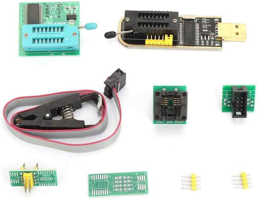
The full set is now available at our online shop.
-
CH341A kit with 1.8V level-shifter. Can be bought on e.g. Amazon
-
Female-female 2.54mm to 2mm dupont wires.
-
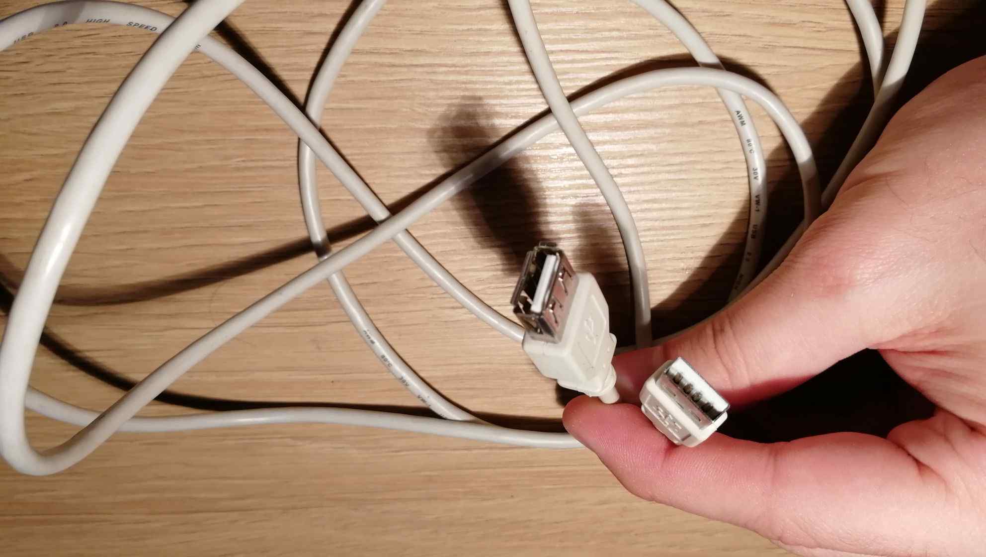
USB2.0 Female-Male extension cord 0.5m or longer (optional)
-
Machine with Linux and flashrom.
Connection
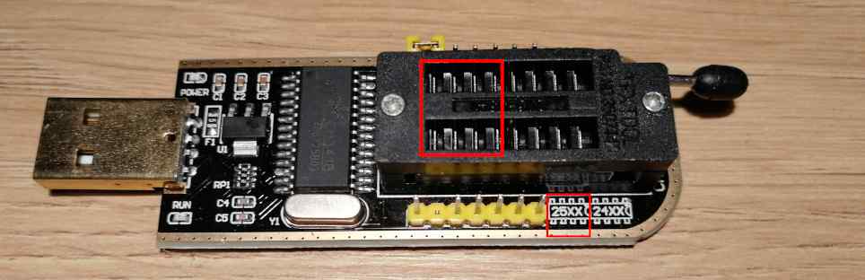
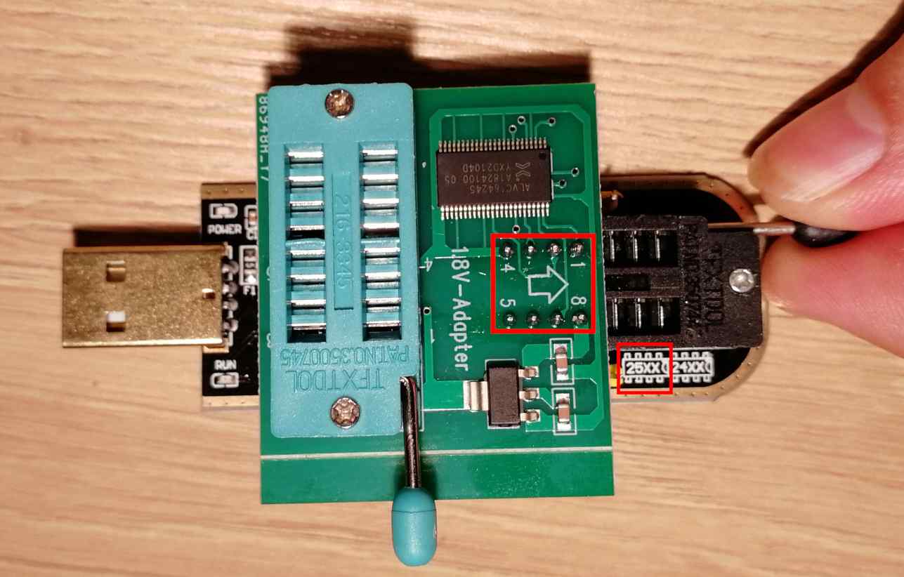
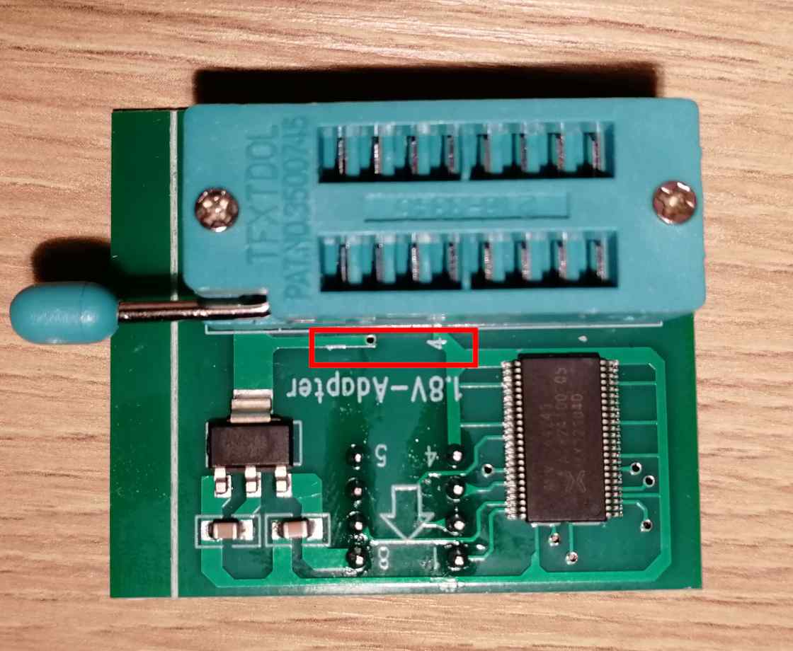
First start with assembling the CH341A and the 1.8V adapter. Pay attention to which holes you attach the adapter. You should use the holes marked as 25XX (closer to the USB plug):
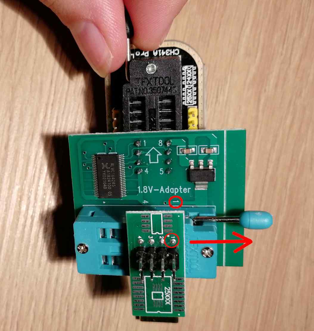
Place the 1.8V adapter in the holes and lock it with the lever. Be sure that the arrow on the adapter is facing the black lever (opposite side of USB plug):
Now take the breakout board with pin headers:
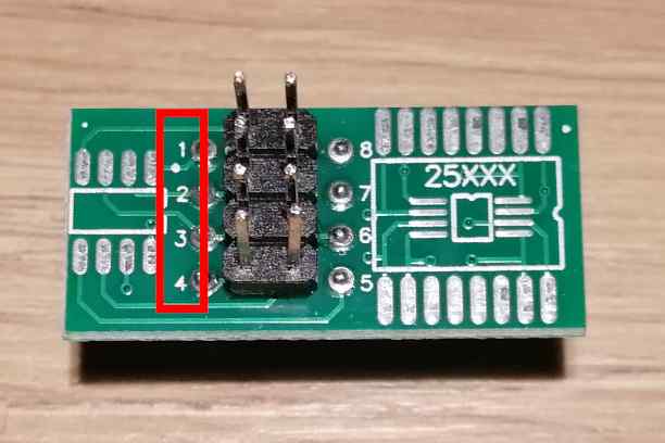
and plug it into the other 1.8V adapter, be sure that numbers 1-4 on the breakout board match the numbers 1 and 4 on the adapter:
Numbers should be visible on the upper side after assembling:
Next, take the dupont wires and connect them to the brekaout board and mainboard's JTPM1 header. The JTPM1 pin5 is actually BIOS SPI CS pin (marked as reserved in the board manual).
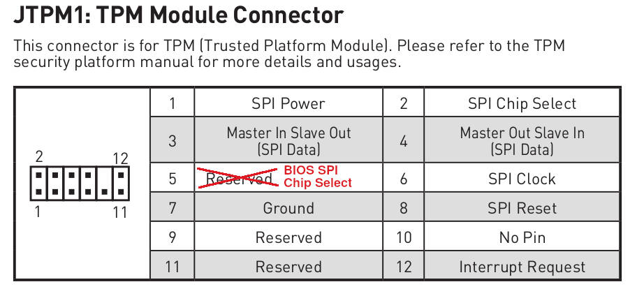
| CH341a breakout board | MSI Z690-A/Z790-P |
|---|---|
| pin 1 (CS) | JTPM1 pin 5 (RESERVED / BIOS SPI CS pin) |
| pin 2 (MISO) | JTPM1 pin 3 (MISO) |
| pin 4 (GND) | JTPM1 pin 7 (GND) |
| pin 5 (MOSI) | JTPM1 pin 4 (MOSI) |
| pin 6 (SCLK) | JTPM1 pin 6 (SPI Clock) |
| pin 8 (Vcc) | JTPM1 pin 1 (SPI Power) |
Now the connection is ready. Time to probe for the flash chip with flashrom.
Flashing
Now on the Linux machine check if the flash is detected using a sample command:
sudo flashrom -p ch341a_spi
You should see something like this:
flashrom v1.2-567-gf4eb405 on Linux 5.19.9-200.fc36.x86_64 (x86_64)
flashrom is free software, get the source code at https://flashrom.org

Using clock_gettime for delay loops (clk_id: 1, resolution: 1ns).
Found Winbond flash chip "W25Q256.W" (32768 kB, SPI) on ch341a_spi.
No operations were specified.
If the flash is detected as above invoke the real flashing command
(e.g. if your original/working firmware backup is saved as
firmware_backup.bin):
sudo flashrom -p ch341a_spi -w firmware_backup.bin
Note that USB programmers are pretty slow, the whole operation make take several minutes (can be 10-15 minutes in worst case). At the end of operation you should see:
flashrom v1.2-567-gf4eb405 on Linux 5.19.9-200.fc36.x86_64 (x86_64)
flashrom is free software, get the source code at https://flashrom.org

Using clock_gettime for delay loops (clk_id: 1, resolution: 1ns).
Found Winbond flash chip "W25Q256.W" (32768 kB, SPI) on ch341a_spi.
Reading old flash chip contents... done.
Erasing and writing flash chip... Erase/write done.
Verifying flash... VERIFIED.
SMBIOS unique data recovery
Serial number format and recovery
SMBIOS specification sections 7.2 and 7.3 defines two spaces for serial number: the system serial number and baseboard serial number. The original MSI PRO Z690-A firmware provides only the baseboard serial number.
In case you have lost your serial number in the process of flashing Dasharo or newer MSI firmware, there is a way to retrieve it. The board has a QR code printed on the mainboard between the chipset heatsink and dPGU PCIe slot:
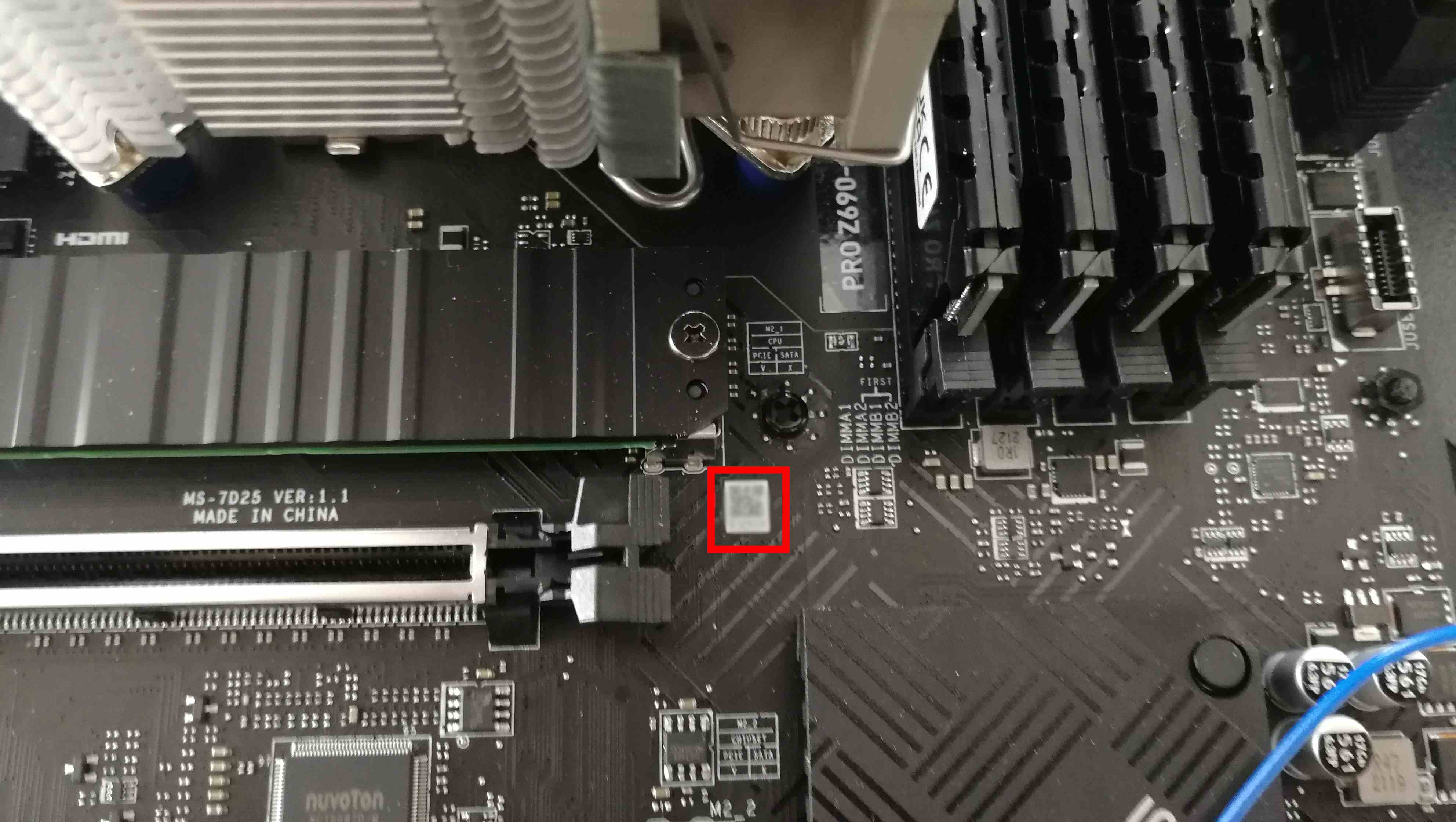
If you read the QR code with your smartphone you will get the full serial
number. The serial number has the format 07D25xx_LyzEaaaaaa where:
07D25- is the board model, i.e. MS-7D25 for this particular boardxxis the mainboard revision which should match the revision imprinted between the M2_1 slot and dGPU slot. E.g.xx=11means VER:1.1yzis the manufacturing date in hex, i.e.yis the month,zis the year, for exampleA1means October 2021,12means January 2022aaaaaais the unique 6-digit number which is imprinted under the serial number QR code
System UUID format and recovery
SMBIOS specification section 7.2 defines a field for unique system identification with a special number called UUID (Universally Unique IDentifier). UUID is specified by RFC 4122. MSI firmware provides the system UUID in the SMBIOS system information structure.
The problem with UUID is that it cannot be recovered if the backup binary or
SMBIOS logs are lost. You can backup the SMBIOS information with our Dasharo
Tools Suite
bootablestick.
The dmidecode.log will have all the necessary information. Things we know
about MSI system UUID:
- UUID format is as follows:
33221100-5544-7766-8899-AABBCCDDEEFF, the hex numbers represent the order of bytes in memory for the little-endian format as required by SMBIOS - MSI UUIDs do not conform to any of the RFC 4122 UUID variants/versions (the bits responsible for UUID version and variant identification are not constant across multiple boards)
- the last octet group
AABBCCDDEEFFis equal to the MAC address of the on-board Intel i225 Ethernet, so be sure to NOT share the UUID with anybody as it contains system sensitive information - the first four groups are either random numbers or some cryptographically acquired value from e.g. combination of some board data, unfortunately it is not known by us
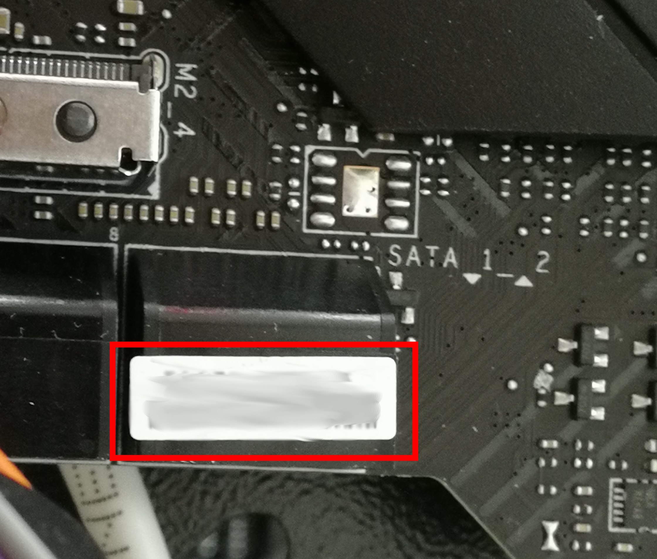
The MAC address is printed on a sticker placed on the 2x2 SATA connector:
SMBIOS data migration
For Dasharo simply follow the Initial Deployment how to migrate the data.
For MSI firmware you will probably need an AMI DMI/SMBIOS editor to save those values back if you do not have a backup binary.