Presale device assembly and validation
Introduction
This document describes the assembly procedure of the PiKVM (device based on Raspberry Pi 4 or Raspberry Pi Zero 2W) with components specified in requirements.
Requirements
Note that the PiKVM build might be basing on two types of Raspberry Pi: RPi 4 or RPi Zero 2W.
Hardware components necessary to build PiKVM on RPi Zero 2W:
- Raspberry Pi Zero 2W,
- microSD card 16 GB,
- USB-A 5 V 3.1 A charger (female socket),
- HDMI to CSI-2 bridge,
- Raspberry Pi Zero Camera Cable,
- HDMI-HDMI cable,
- USB A - micro USB cable (male, male),
- Y-splitter cable.
- (Optional) UART -> USB converter
Hardware components necessary to build PiKVM on RPi 4:
- Raspberry Pi 4,
- microSD card 16 GB,
- USB-A 5 V 3.1 A charger (female socket),
- HDMI to CSI-2 bridge,
- HDMI-HDMI cable,
- USB A - USB C cable,
- Y-splitter cable.
- (Optional) UART -> USB converter
Device assembly
The following section of the documentation shows the assembly procedure for PiKVM including setting up a WiFi connection and methods for reading device IP.
Set based on RPi Zero 2W preparation
The section below describes the method of preparing PiKVM hardware based on RPI Zero 2W.
-
Connect SD card and HDMI to CSI-2 bridge with camera cable:
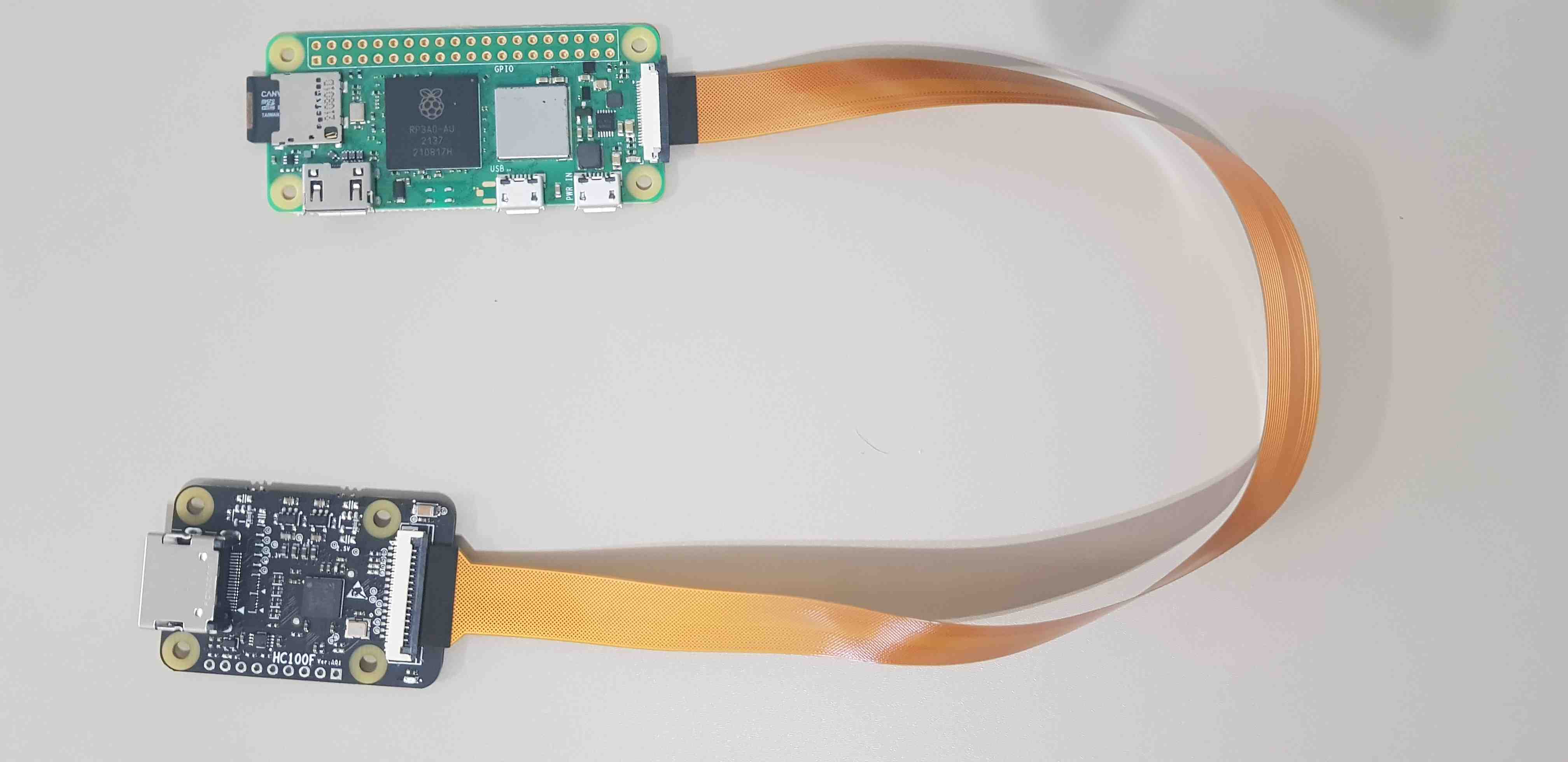
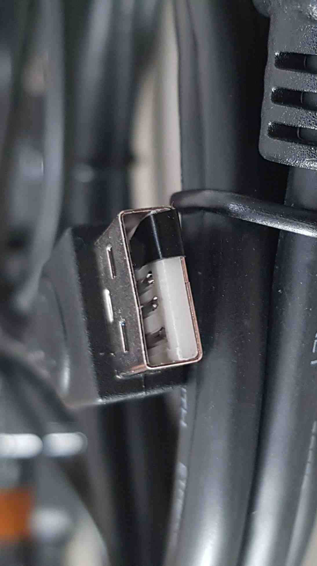
-
Block USB power from device under test by preparing USB cable:
-
Connect HDMI cable from the device under test to HDMI -> CSI-2 bridge.
- Connect the USB splitter to the Raspberry Pi micro USB port.
- Connect one side of the splitter to USB-A 5 V 3.1 A charger.
- Connect other side to device under test via USB cable with blocked power.
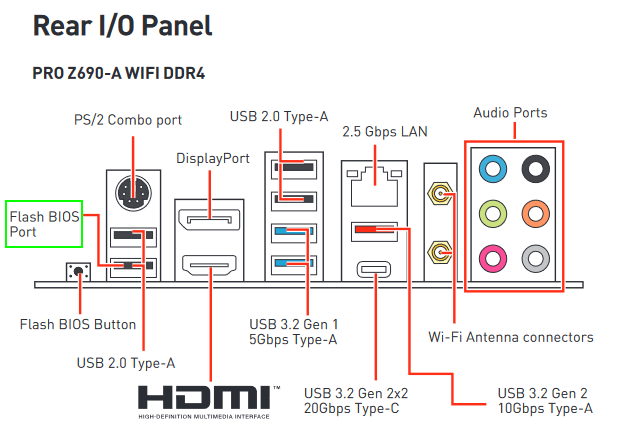
NOTE: When setting up PiKVM for an MSI platform, remember to avoid the Flash BIOS USB port, as it can generate problems with the flashing procedure. Always refer to the mainboard's manual for the port's location, as in the example below.
Set based on RPi 4 preparation
To build PiKVM on RPi 4, use the RPI 0 set documentation and replace the cable for connecting to the RPi and the cable for connecting with the CSI-2 bridge.
OS image building and flashing
-
Prepare the OS in accordance with the PiKVM Handbook.
-
Flash the SD card using
bmaptoolorbalenaEtcher.- to do this by
balenaEtchergo to the producer site and follow his procedure on how to download and flash an SD card. -
to do this by
bmaptoolreproduce the following steps:-
install
bmaptoolby opening the terminal and typing the following command:sudo apt install bmap-tools -
create the bmap by typing the following command:
bmaptool create /path/to/your/image > /path/where/you/want/bmap/file/saved/bmapfilename.bmap -
flash image to the SD card by typing the following command:
sudo bmaptool copy --bmap ~/path/where/your/bmap/file/is/located /path/where/your/image/is/located /path/to/memory/device
-
- to do this by
-
Insert the flashed SD card into the SD card slot on the PiKVM.
Set up WiFi
The section below describes the method of setting up a WiFi connection for the PiKVM. This section is dedicated especially to the PiKVMs based on RPi Zero 2W, which is not equipped with an Ethernet port.
-
Mount the first partition of the memory card.
-
Edit or make the
pikvm.txtfile in the following convention:FIRSTBOOT=1 WIFI_ESSID="name" WIFI_PASSWD="password"Note: Do not remove line
FIRSTBOOT=1orFIRST_BOOT-1line. It may occur with troubles with the device starts. -
Unmount the first partition of the memory card.
Note: In some countries, in which WiFi channel 13 is in use, the device might not connect to the WiFi. To prevent this, the router should be configured properly: channels 12-14 or Auto Scan mode should be disabled.
Read IP address
The section below describes the known methods of reading PiKVM IP.
-
First option: from
osrepository run the following command:make scanExample output:
. . . ===== Toolbox image is ready ===== ===== Searching for Pis in the local network ===== docker run \ --rm \ --tty \ --net host \ pi-builder-arm-toolbox arp-scan --localnet | grep -Pi "\s(b8:27:eb:|dc:a6:32:)" || true 192.168.4.13 dc:a6:32:aa:aa:aa Raspberry Pi Trading Ltd -
Second option: open the web interface of your router and find the list of issued IP addresses. Localization of the mentioned list depends on the router model.
-
Third option:
-
solder pins for serial output as on images below:
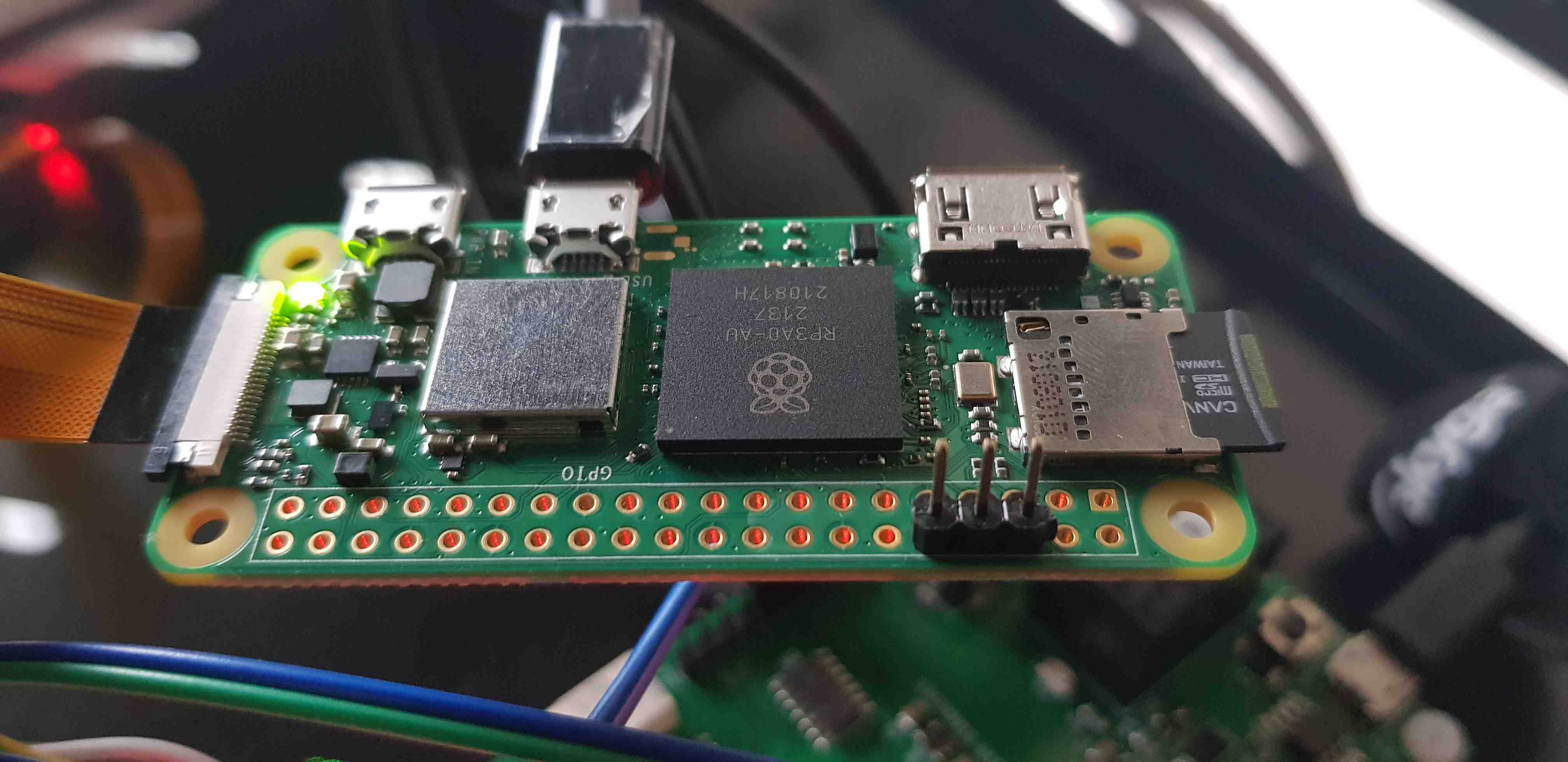
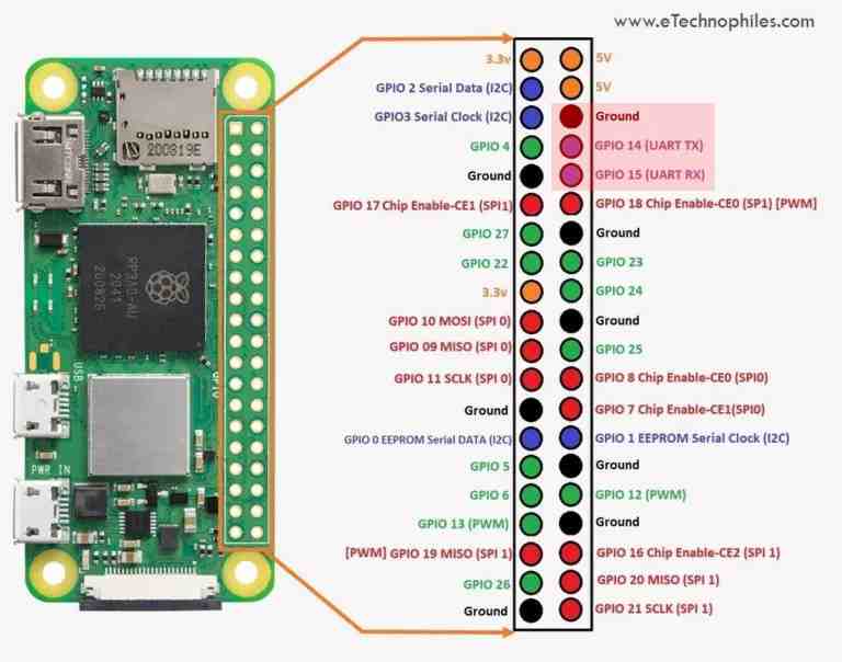
-
Check Raspberry Pi Zero2W IP by booting to system and reading information via serial (eg.) UART -> USB converter.
-
Device validation
- Connect the device to the mains.
- Login to RTE via
ssh(by using earlier obtained IP address) orminicom(by using USB-UART converter with 3 wire cables).
FullHD stream
In order to enable FullHD stream (1920x1080) instead of 1200x720. One of the reasons to enable FullHD is that certain proprietary BIOSes implement a GUI setup which scales well only for Full HD or higher resolutions (in extreme cases it can even crash if lower than FullHD resolution is used).
To enable FullHD resolution, one has to replace the EDID on PiKVM. To do so:
- Remount the filesystem to RW if necessary using
rwcommand. -
Save the follow HEX to
/root/edid.hex:00FFFFFFFFFFFF005262888800888888 1C150103800000780AEE91A3544C9926 0F505425400001000100010001000100 010001010101D32C80A070381A403020 350040442100001E7E1D00A050001940 3020370080001000001E000000FC0050 492D4B564D20566964656F0A000000FD 00323D0F2E0F000000000000000001C4 02030400DE0D20A03058122030203400 F0B400000018E01500A0400016303020 3400000000000018B41400A050D01120 3020350080D810000018AB22A0A05084 1A3030203600B00E1100001800000000 00000000000000000000000000000000 00000000000000000000000000000000 00000000000000000000000000000045 -
Execute:
kvmd-edidconf --edid=/root/edid.hex --apply - Execute:
kvmd-edidconf --import=/root/edid.hex - Switch the filesystem back to RO using
rocommand.
When PiKVM is connected to the platform, the BIOS or OS should initialize the display with 1920x1080 resolution.
Where to buy?
The PiKVM is available in our online shop.