Recovery
Introduction
The following documentation describes the process of recovering NovaCustom platforms from the brick state. This procedure can be used to restore both Dasharo and previous Insyde/AMI firmware. This procedure can be used to restore both Dasharo and previous Insyde/AMI firmware.
Prerequisites
Warning
To proceed with the recovery procedure, the backup with the vendor firmware or
vendor EC firmware will be necessary eg. bios_backup.rom, ec_backup.rom.
The backup file should be generated before making any changes to the device flash chip according to the following documentation sections:
Restoring vendor BIOS requires restoring a compatible version of EC firmware. There is currently no way to do this internally.
Necessary components
You will need:
- a CH341a programmer with 3.3V support
- a SOIC-8 (Pomona) clip
You will need:
- a CH341a programmer with 3.3V support
- a WSON-8 probe
You will need:
- a CH341a programmer with 1.8V support
- a WSON-8 probe
A complete set containing everything you need is available from our shop.
Follow the Initial deployment
section to perform the external flash. When running the flashrom commands, use a
backup file you've prepared previously, like bios_backup.rom.
You will need:
- an Arduino Mega 2560
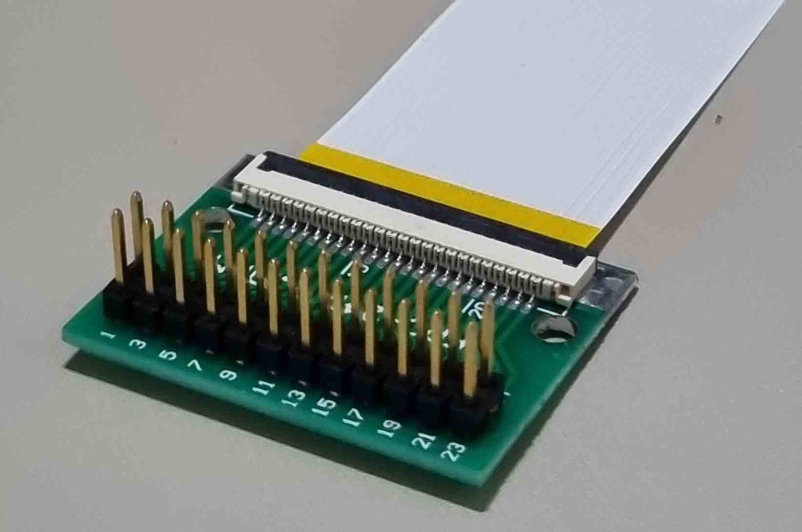
- a 24-pin FFC cable with a 1.0mm pitch, same-sided (connectors on the same side on both ends of the cable)
- a 24-pin FFC breakout board with a 1.0mm pitch FFC connector and a 2.54mm pitch pin header
- USB-A to USB-B cable to connect the Arduino to the host
- USB-C cable for grounding with power blocker
You will need:
- an Arduino Mega 2560
- a 24-pin FFC cable with a 0.5mm pitch, same-sided (connectors on the same side on both ends of the cable)
- a 24-pin FFC breakout board with a 0.5mm pitch FFC connector and a 2.54mm pitch pin header
- USB-A to USB-B cable to connect the Arduino to the host
- USB-C cable for grounding with power blocker
You will need:
- an Arduino Mega 2560
- a 24-pin FFC cable with a 1.0mm pitch, same-sided (connectors on the same side on both ends of the cable)
- a 24-pin FFC breakout board with a 1.0mm pitch FFC connector and a 2.54mm pitch pin header
- USB-A to USB-B cable to connect the Arduino to the host
- USB-C cable for grounding with power blocker
The full set for EC firmware recovery is available at our online shop.
EC firmware recovery
The procedure will be slightly different depending on the model of your laptop.
Danger
Ensure you choose the correct FFC cable, as they can be easily damaged. Needed components
Important
Make sure your battery is connected for this process.
Prerequisites
- Clone the EC repository:
git clone https://github.com/Dasharo/ec.git
cd ec
git submodule update --init --checkout
- Install dependencies:
./scripts/deps.sh
- If
rustupwas installed as part of the previous step, run:
source $HOME/.cargo/env
-
Connect the Arduino to the computer using a USB-A to USB-B cable
-
Build and flash firmware for the Arduino, which will serve as the flasher:
make BOARD=arduino/mega2560
make BOARD=arduino/mega2560 flash
Recovery steps
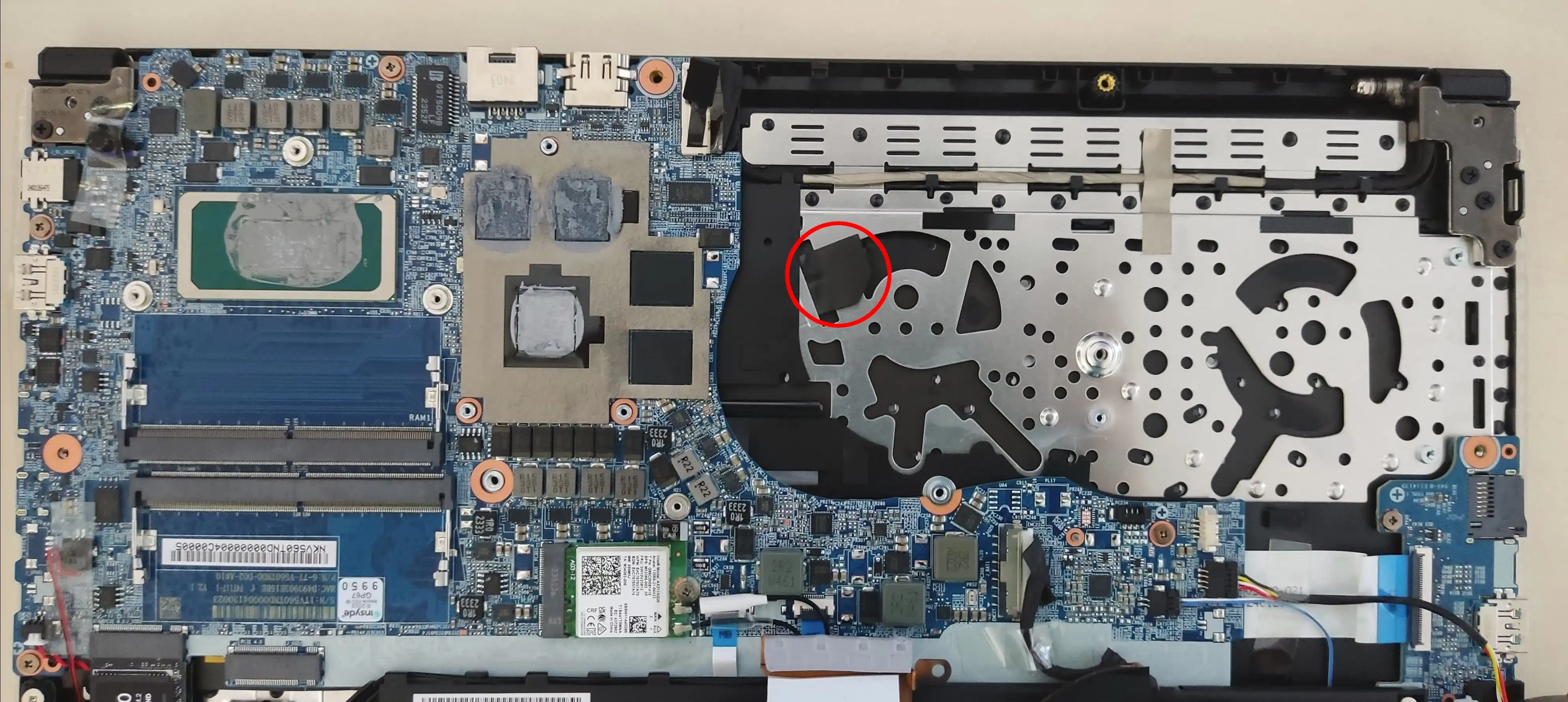
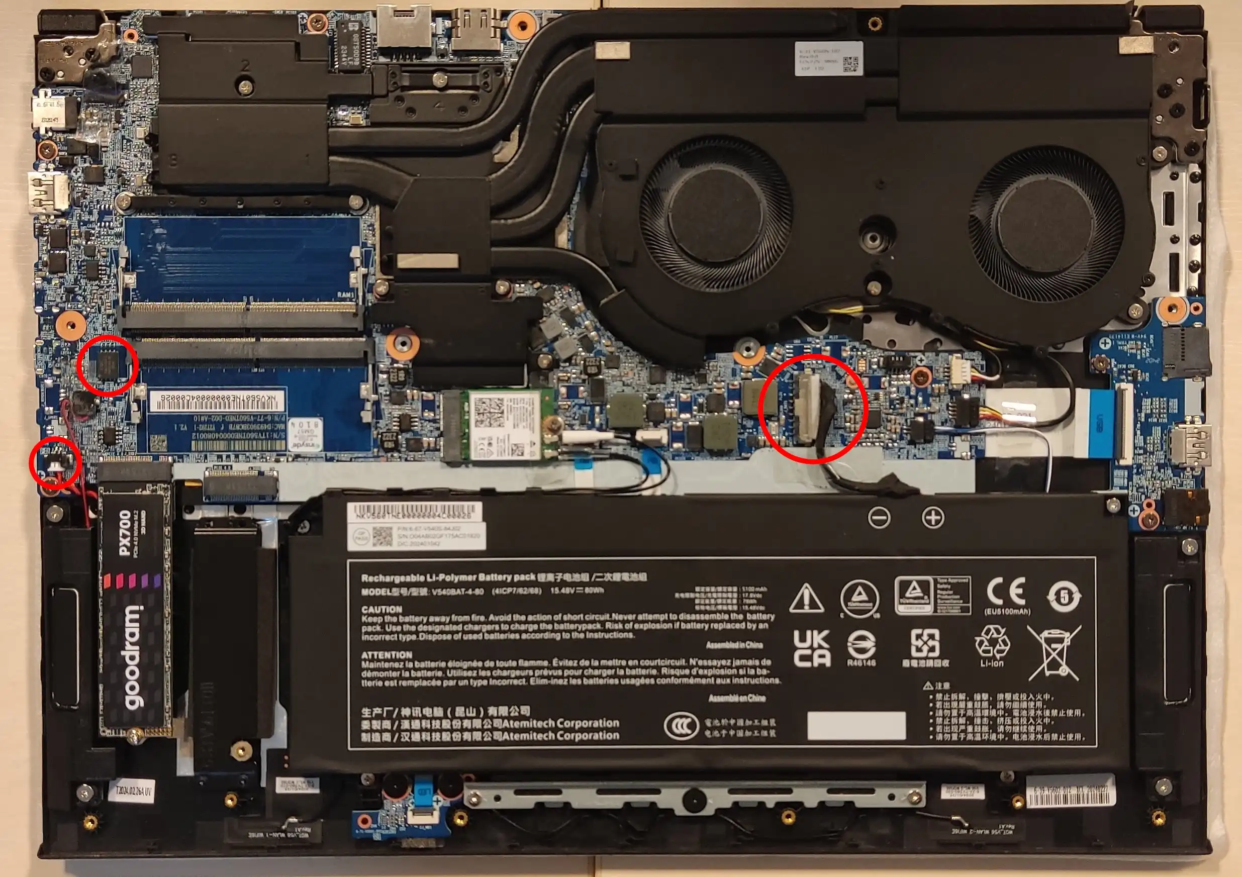
Removing Screws
-
For the V560 laptops you will need to remove two stretch-release pull tabs that are holding keyboard in place.
-
Second pull tab is located under the heat sink.
-
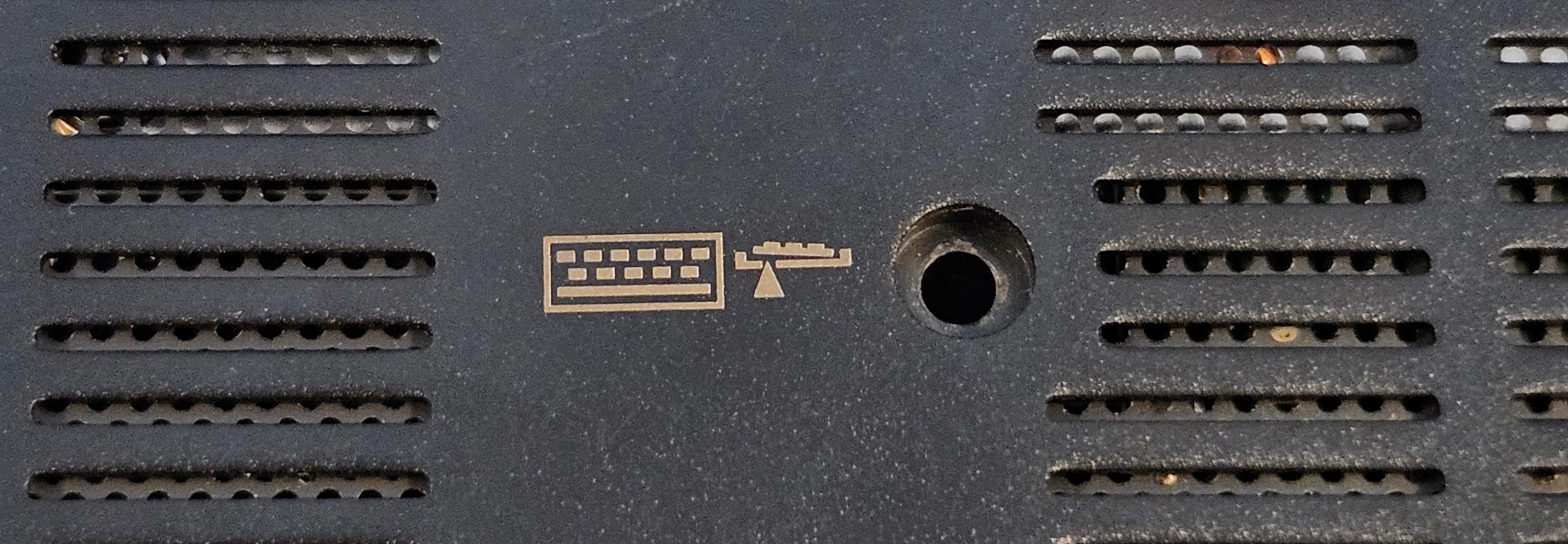
Remove the two screws holding the keyboard in place. They are indicated on the bottom cover with a keyboard symbol:
Connecting
-
Pry the keyboard away from the laptop. Use a plastic spudger to release the tabs holding it in place, starting from the top.
Warning
Be extra careful when removing the keyboard to avoid damaging the fragile keyboard cable!
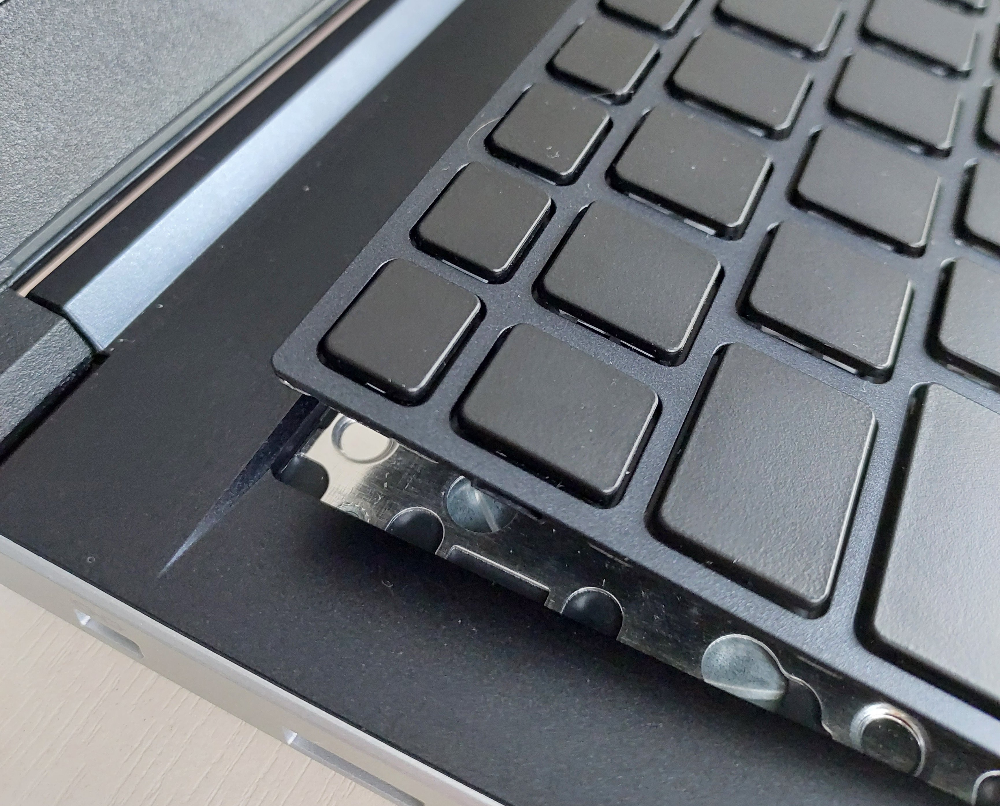
-
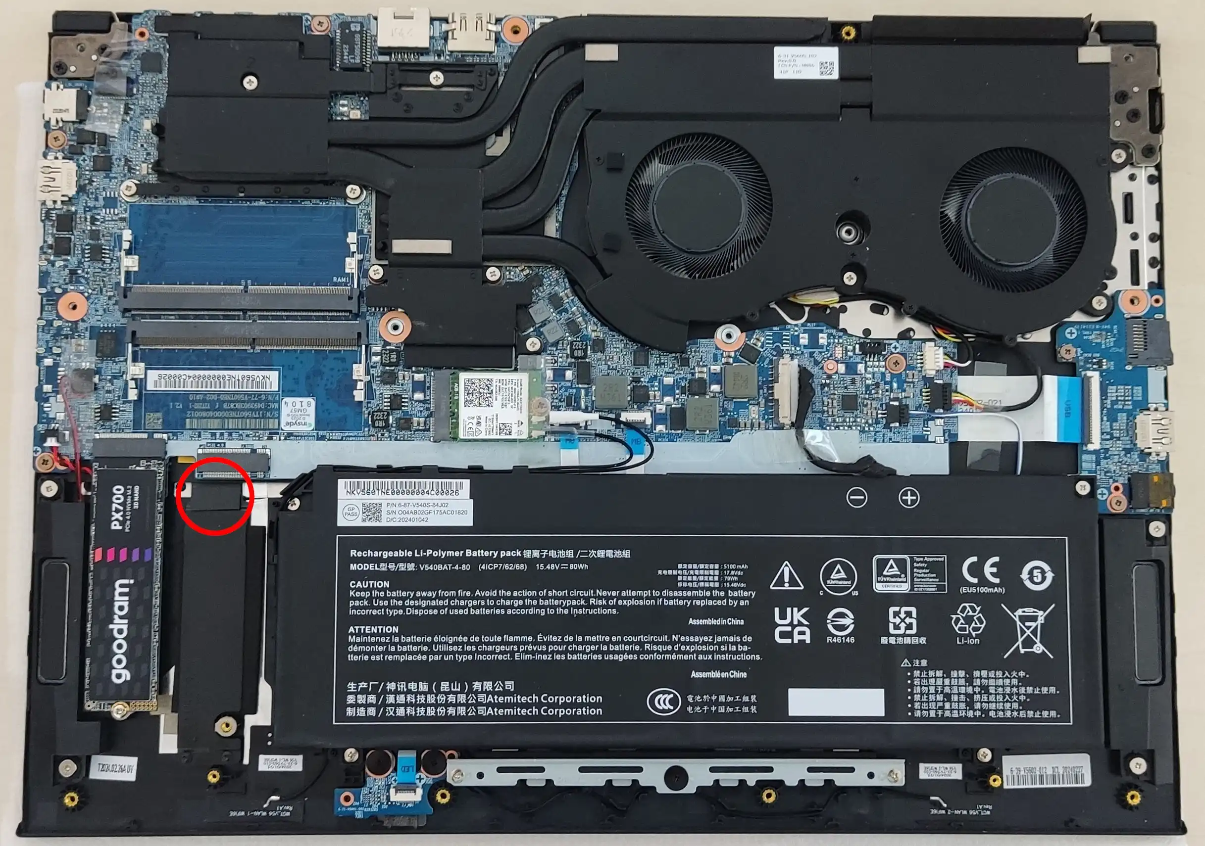
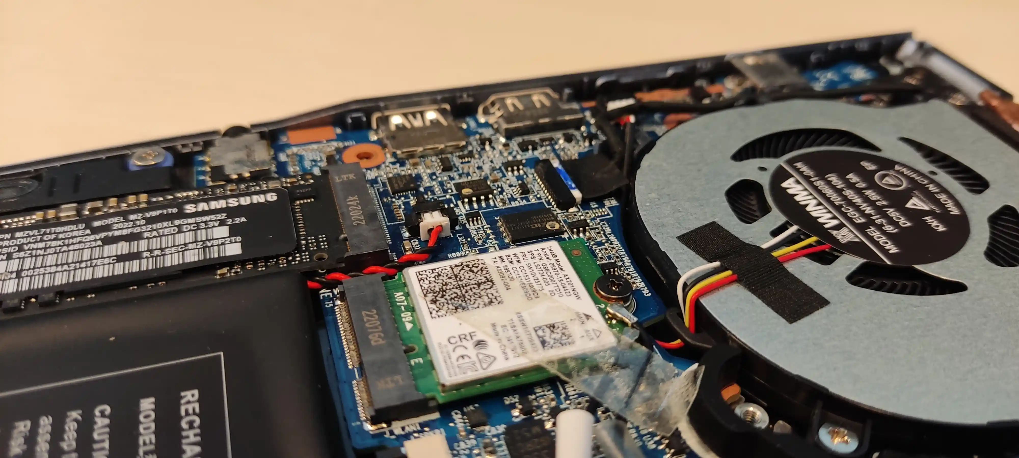
Unplug the keyboard connector by lifting up the tab holding it in place:
-
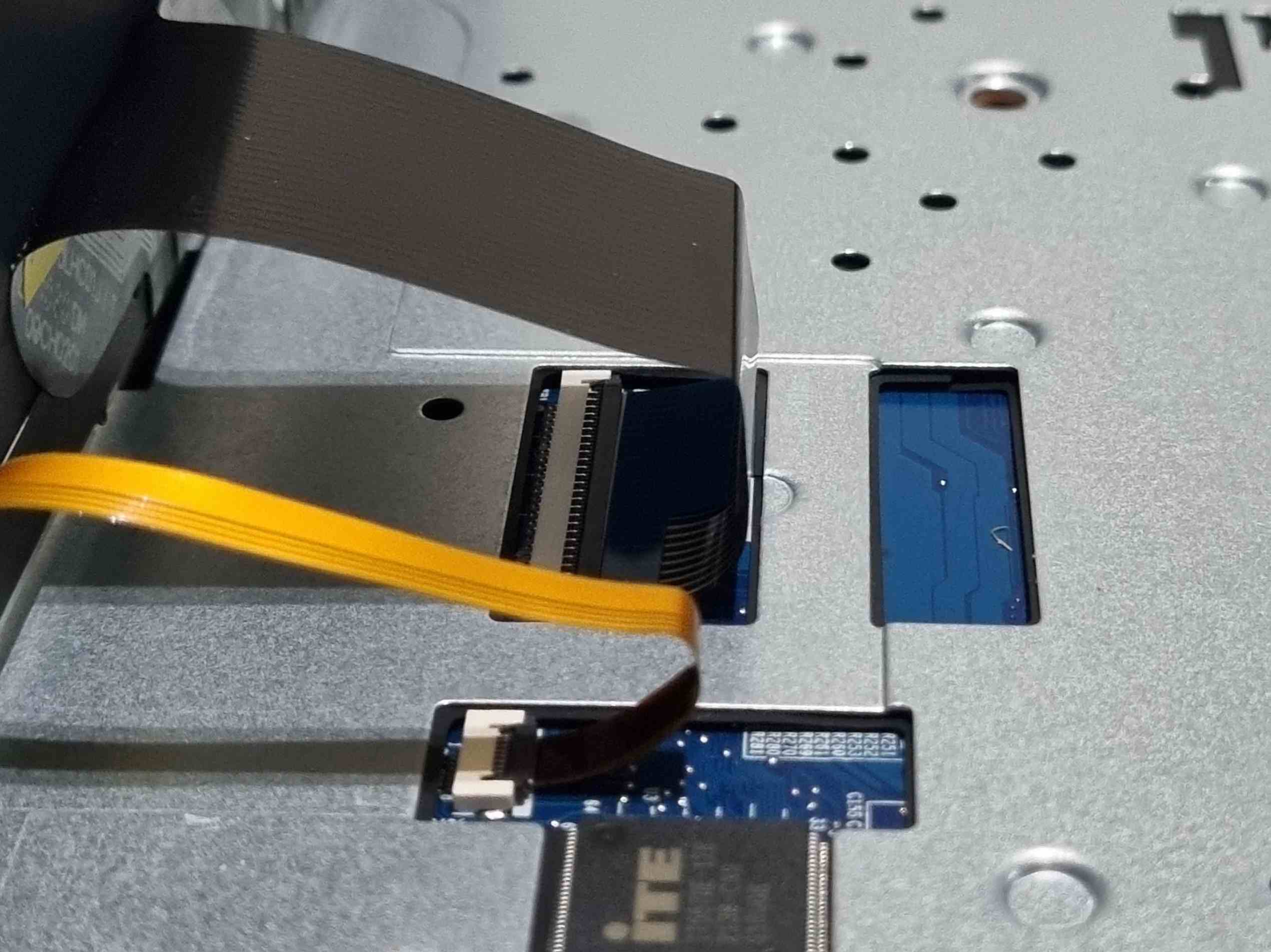
Connect the FFC cable to the FFC breakout board
Warning
In the example above, the FFC connector on the breakout has the pins on the bottom side of the connector and is located on the same side as the pins connecting to the Arduino. If your breakout is different, you may need an FFC cable with connectors on the opposite sides.
-
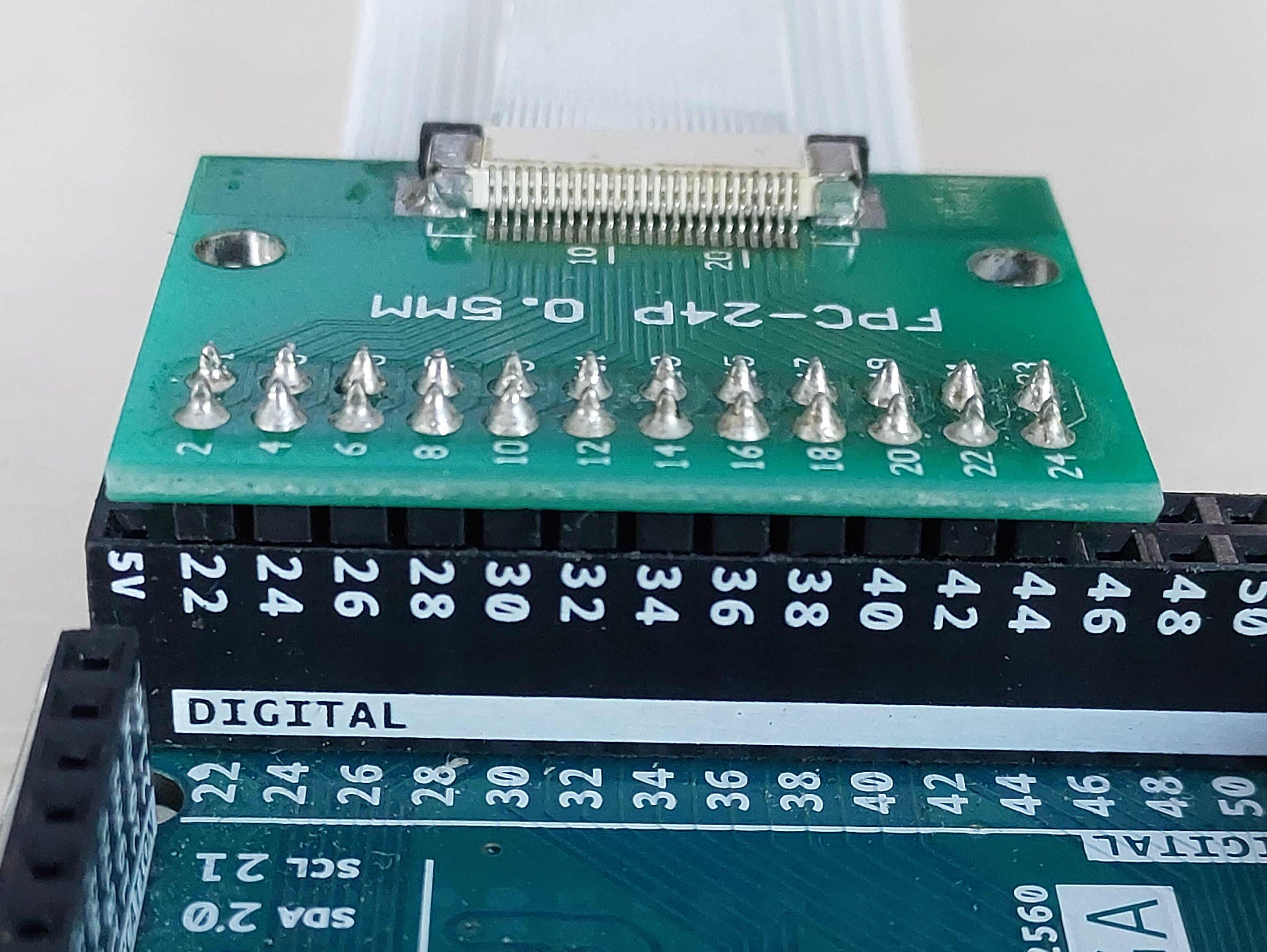
Insert the breakout into Arduino's digital pin header, pins 22-45, with the FFC connector facing outwards
-
Connect the other end of the FFC cable to the keyboard connector on the laptop, taking care to align pin 1 of the FFC cable to pin 1 (leftmost) pin of the connector
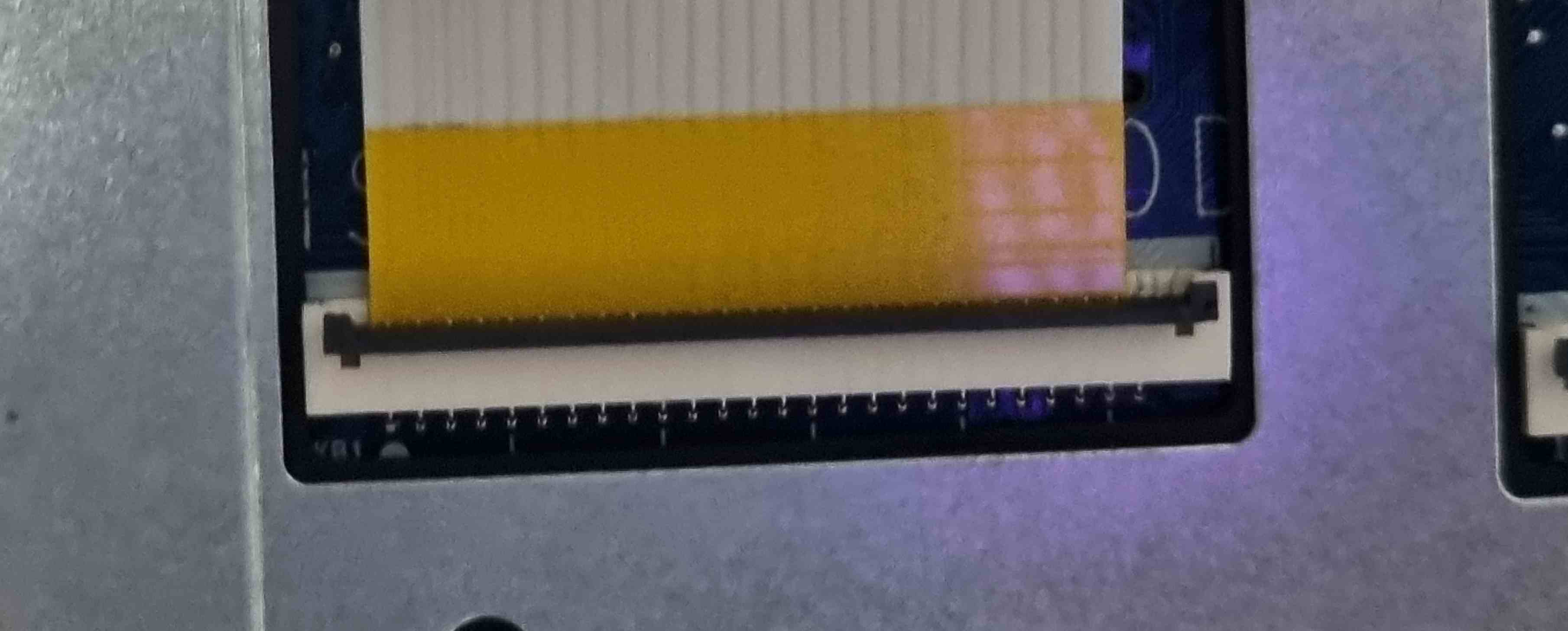 FFC cable with a 1mm pitch
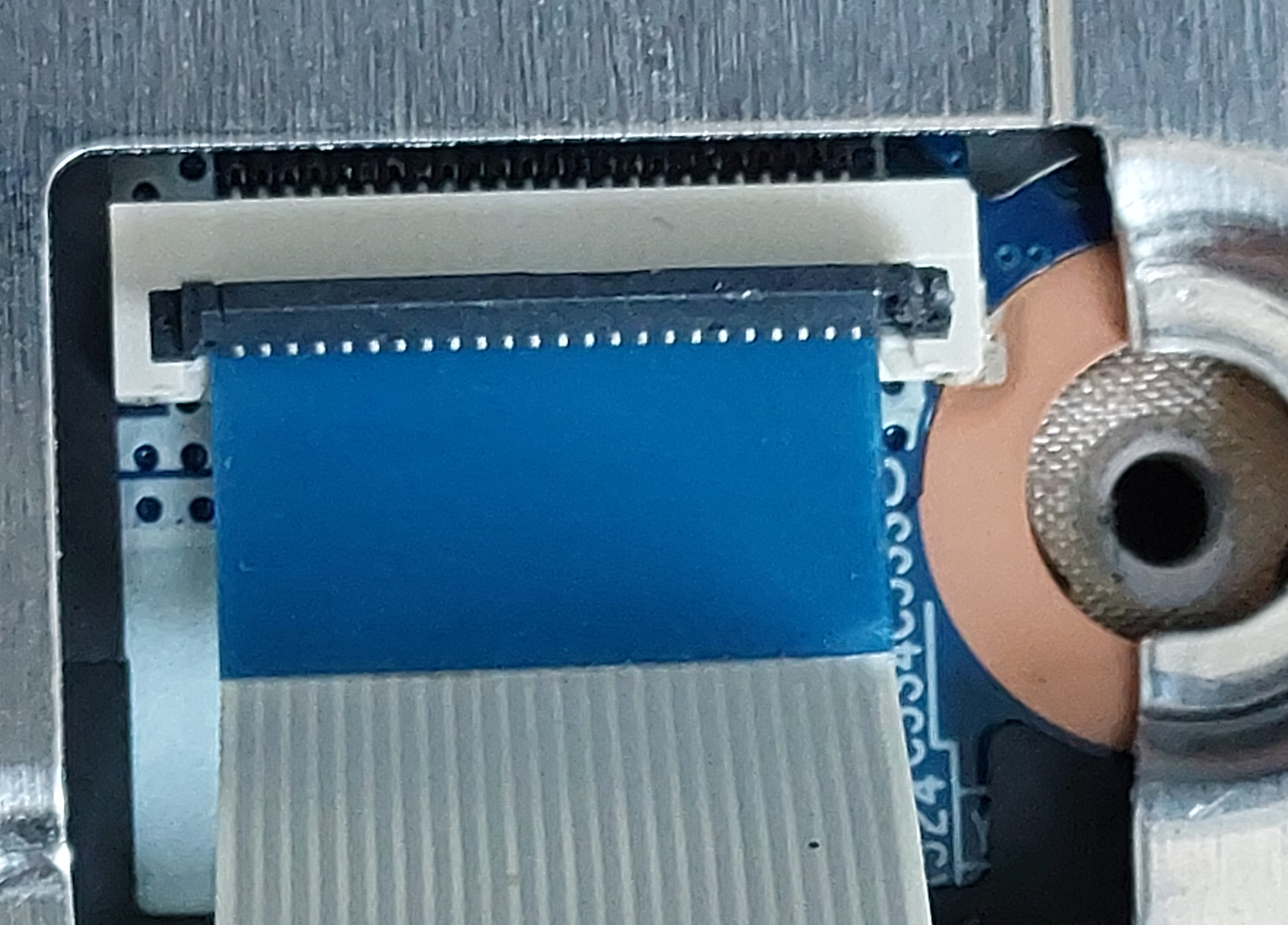 FFC cable with a 0.5mm pitch
 -
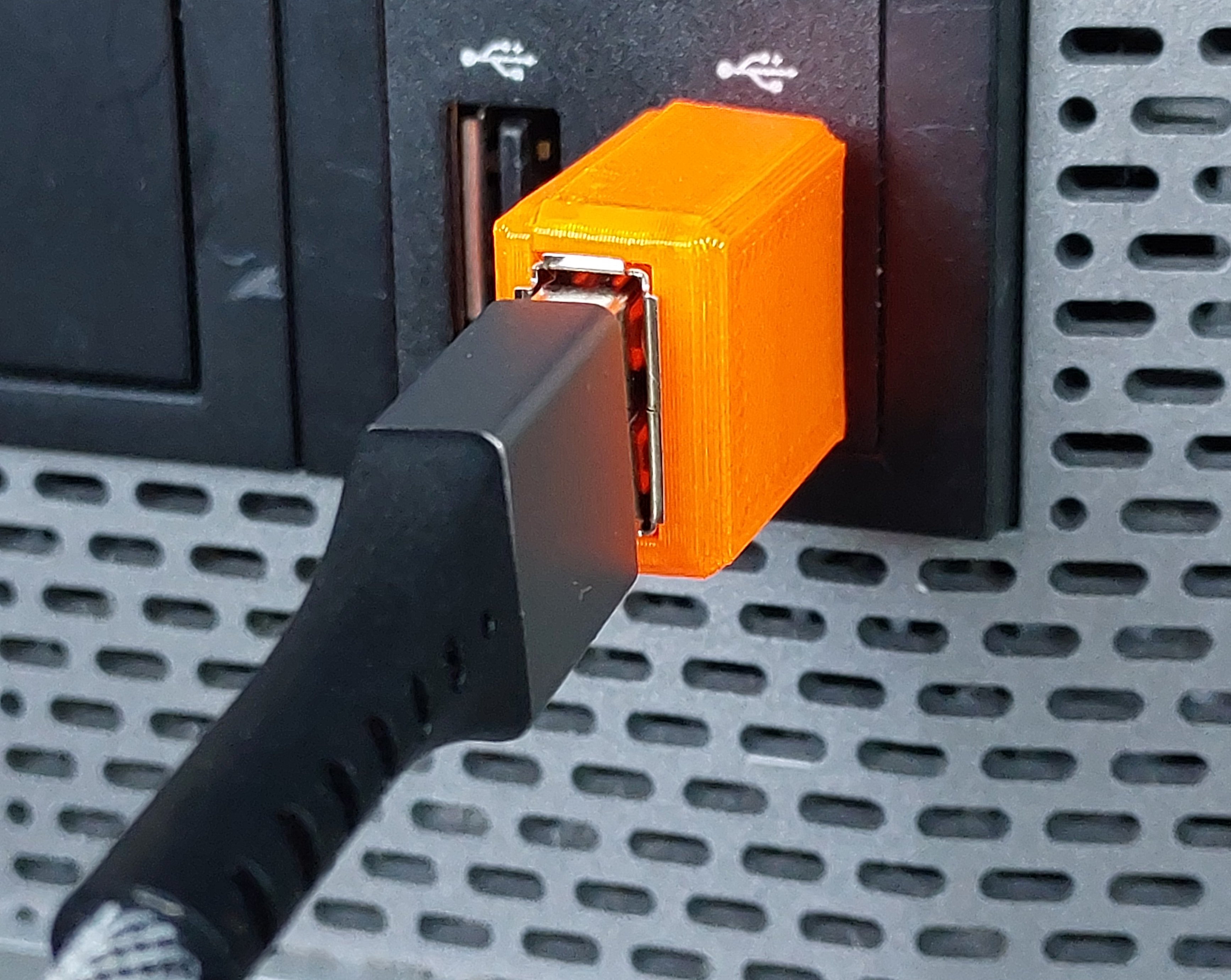
Connect the Arduino to the host using the USB-A to USB-B cable
-
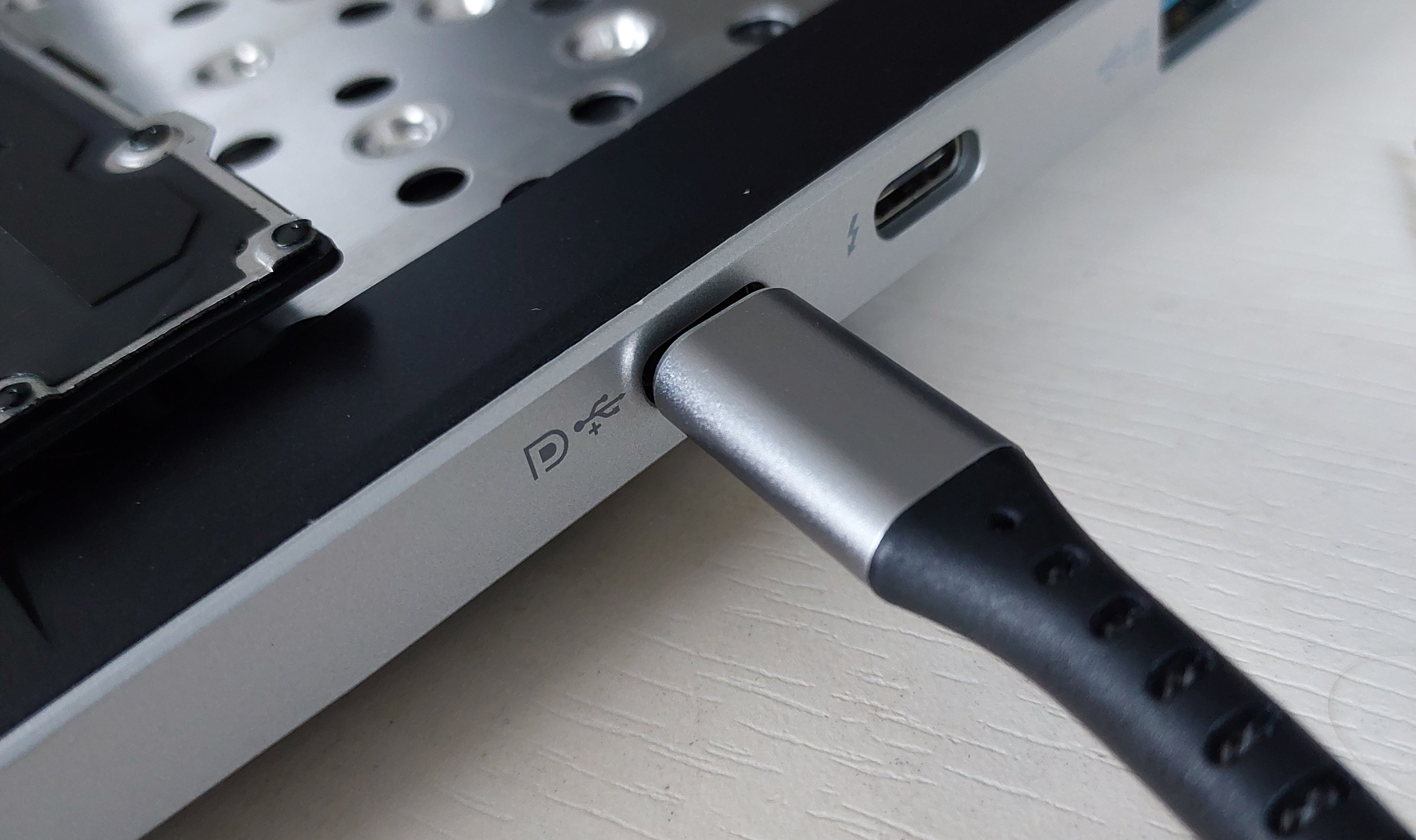
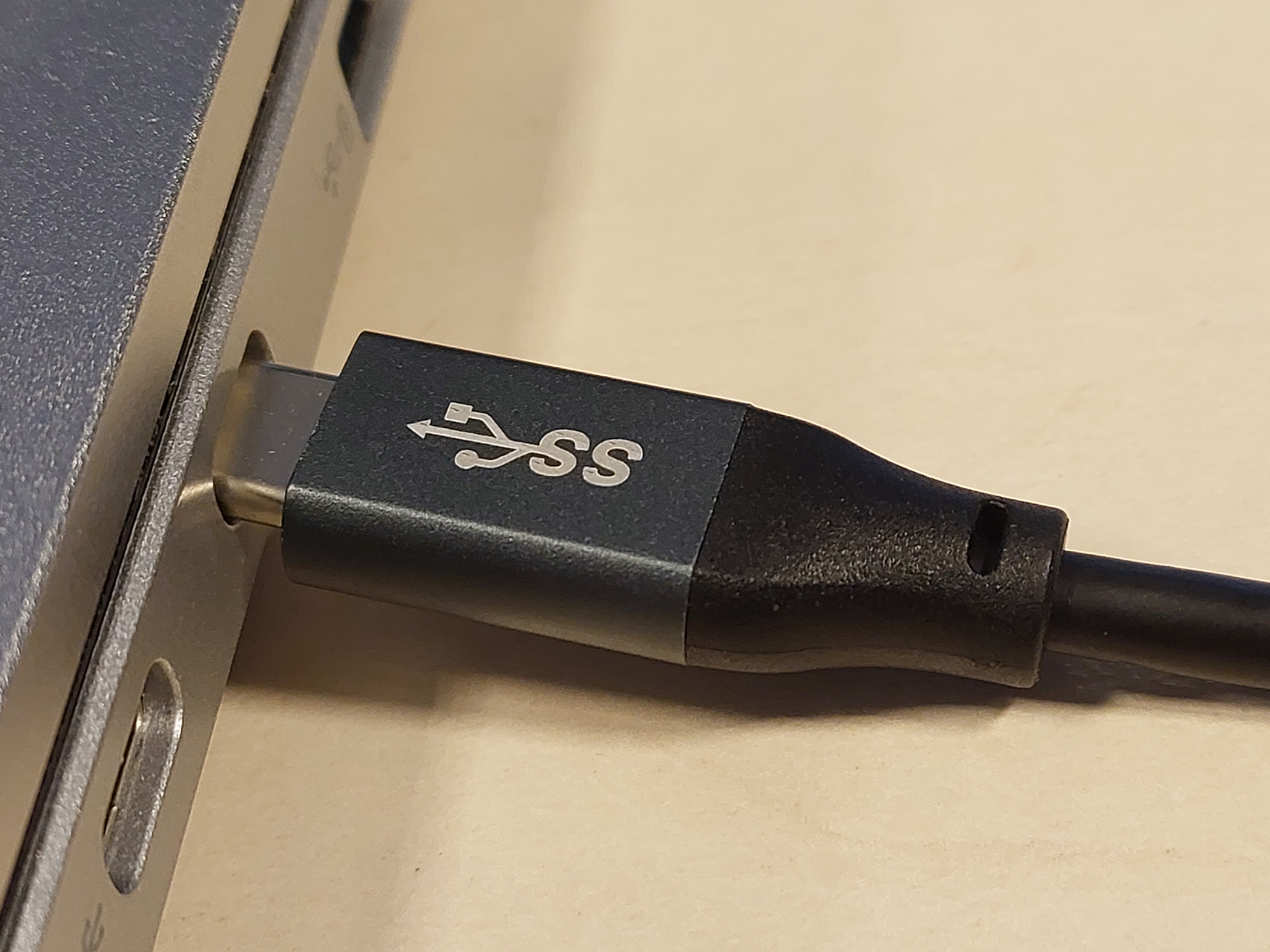
Connect the USB-C cable together with power blocker from your host computer to the laptop.
Warning
This extra cable is for grounding. It's required, because there is no ground signal on the keyboard connector. If you are not using using Power Blocker Ensure the power pin on the cable is taped over to prevent the Embedded Controller chip from getting powered.
Flashing
-
Build the flashing utility:
cargo build --manifest-path ecflash/Cargo.toml --example isp --release -
Flash the firmware:
sudo ecflash/target/release/examples/isp [path to EC binary]The output will contain:
Buffer size: 128
ID: 5570 VER: 2
If it contains other ID value or the connection times out, check all connections, using the photos above for reference.
-
Reassemble the laptop: disconnect the Arduino from the laptop, disconnect the USB-C grounding cable, reinstall the keyboard, reinstall keyboard screws.
EC Recovery troubleshooting tips
Flashing the EC firmware is highly unstable and many small and hard to pinpoint factors might influence it causing the process to fail. Here is a list of known tips and tricks, that are not a part of the official recovery steps, but under some circumstances might help if the flashing fails.
Repeat
Sometimes just repeating the flashing might help and no other steps would be necessary. To make it easier you can use a bash loop like this one:
while ! sudo ecflash/target/release/examples/isp ec.rom; do sleep 1; done
Don't overdo it. If flashing did not succeed after a couple minutes, waiting any longer likely won't help.
Connections
Make sure that everything is connected correctly. Try unplugging and plugging back every cable while running the flashing loop in background.
Repeat all the steps from the beginning
It's easy to skip some essential step like building and flashing the Arduino firmware, or forgetting to use a power blocker or to connect the grounding cable altogether. Before trying any optional tips, please verify that all the baseline instructions were performed with care.
Grounding
Turns out, that sometimes blocking the 5V line on a USB cable is not
enough to keep the laptop not powered. The data lines (D+, D-) can carry
a little bit of current and make the flashing fail.
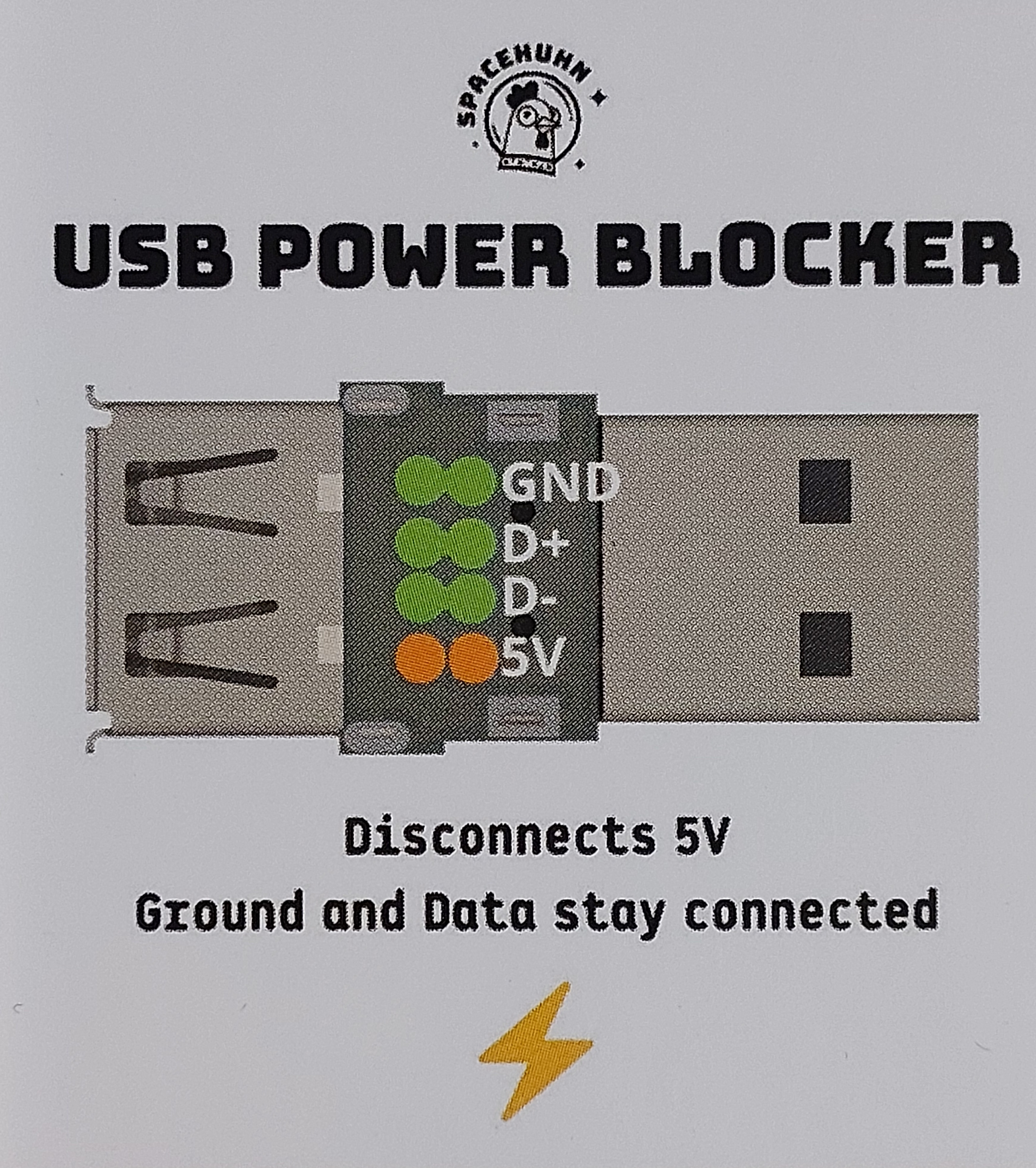
If blocking them is not feasible, try to only slightly lean the connector against the USB-C port on the laptop. Just so that the outer metal part of the connector touches the outer metal part of the charging port. This way the data lines will stay unconnected while a ground connection will be possible to maintain using the metal housing.
Connecting power
These methods can be risky, so leave this option as a last resort when nothing works.
It was found out experimentally, that in some scenarios, when nothing else helps, connecting the internal battery or an AC charger can make the flashing to succeed. Try to flash the EC with the battery connected, and then with an AC charger connected.
A related trick you can try at this point is to connect the AC charger before running the flashing utility, and disconnecting it during the execution. Try to do that a couple times at different moments.
BIOS Flashing
Components Necessary to perform BIOS Recovery: Needed components
Prerequisites
- Flashrom installed on a Linux host
- BIOS image file to flash
Flashing
-
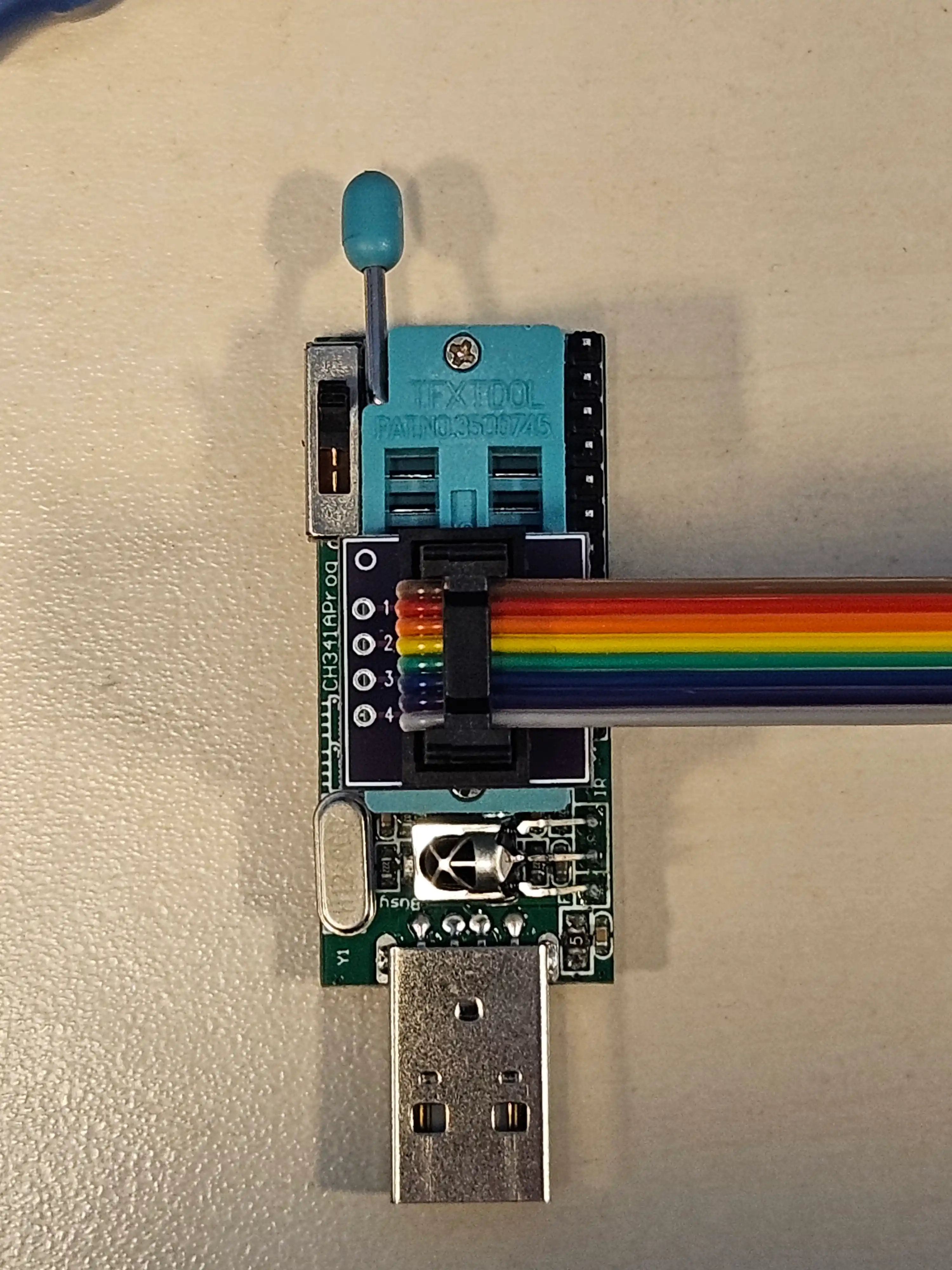
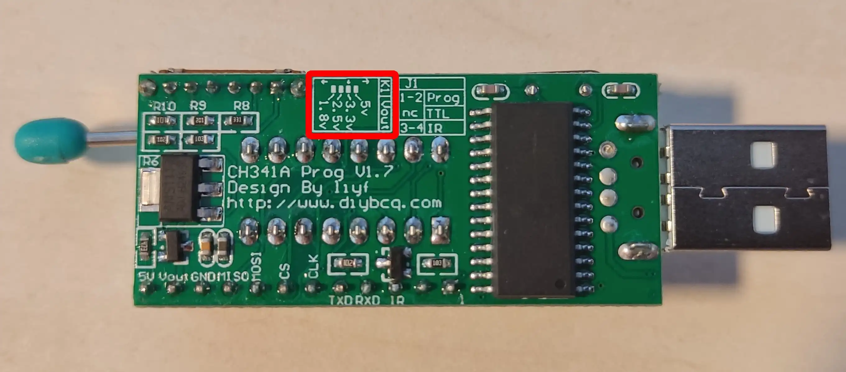
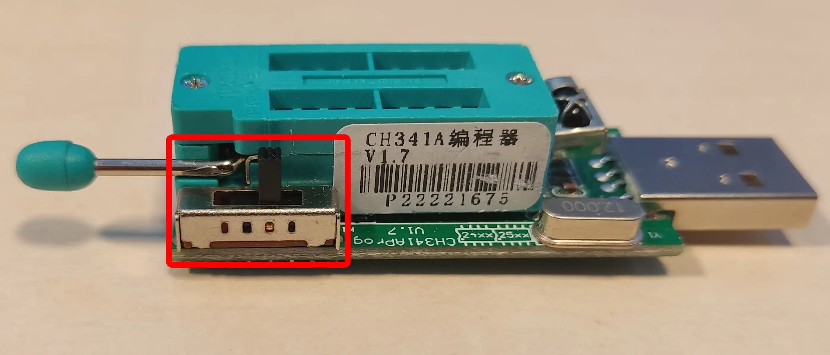
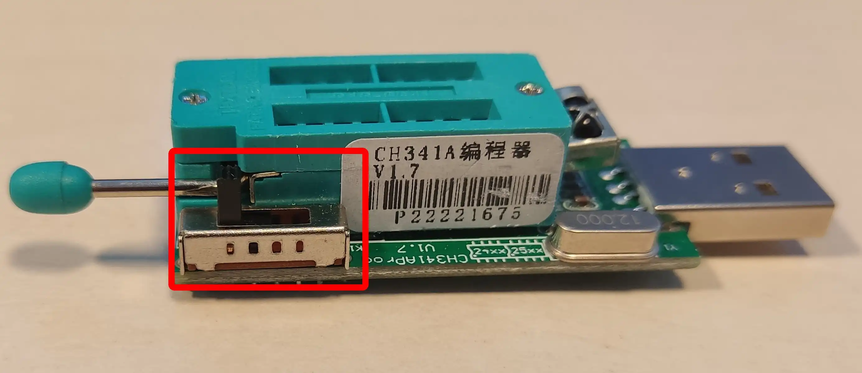
Attach the SOIC-8 Pomona clip to the programmer. Take care to align CS pin with pin 1 on the programmer:
Danger
If your CH341a programmer has a voltage switch, make sure it's at 3.3V. Improper voltage selection may result in hardware damage.
-
Plug the programmer into your host computer.
-
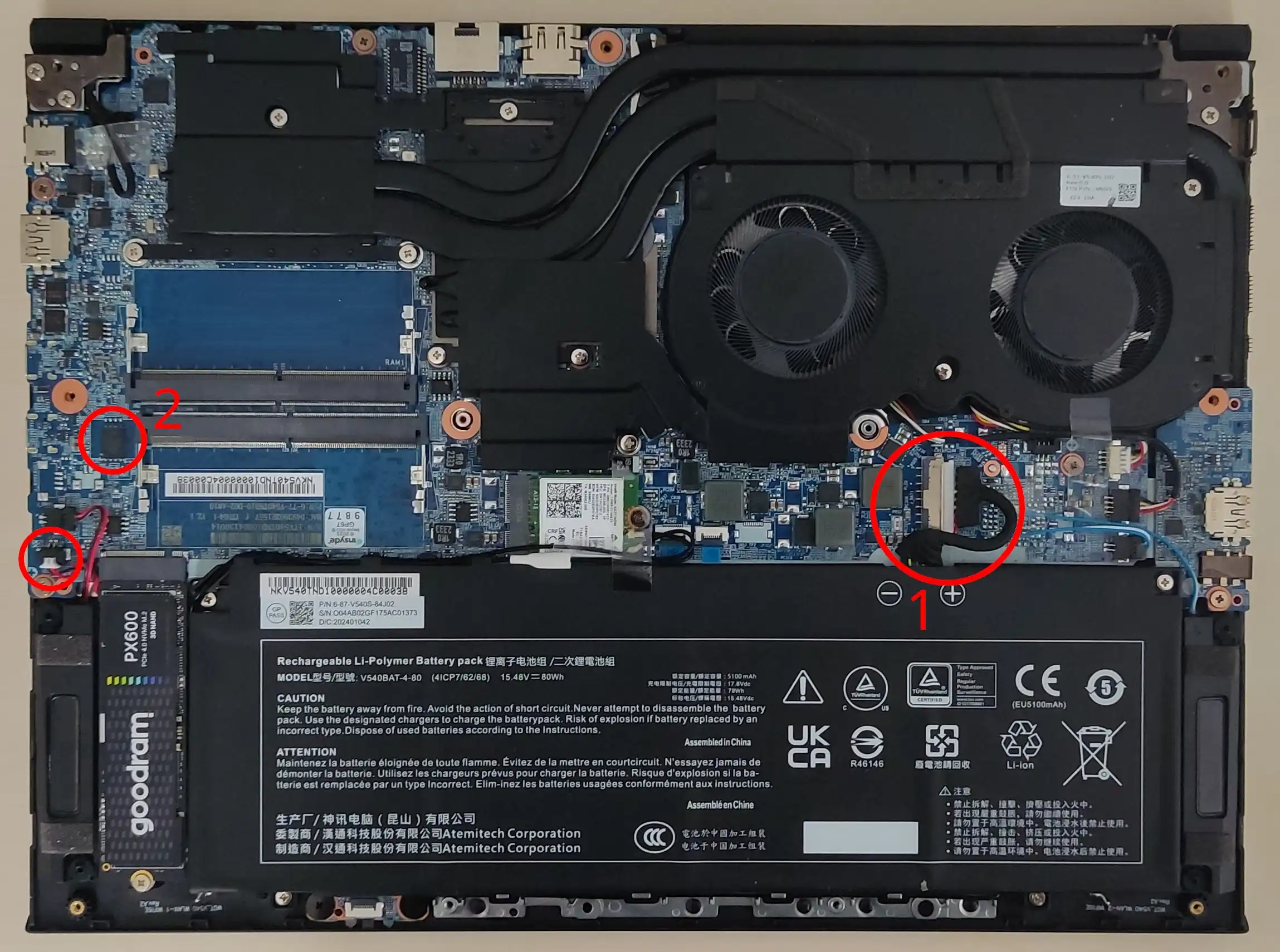
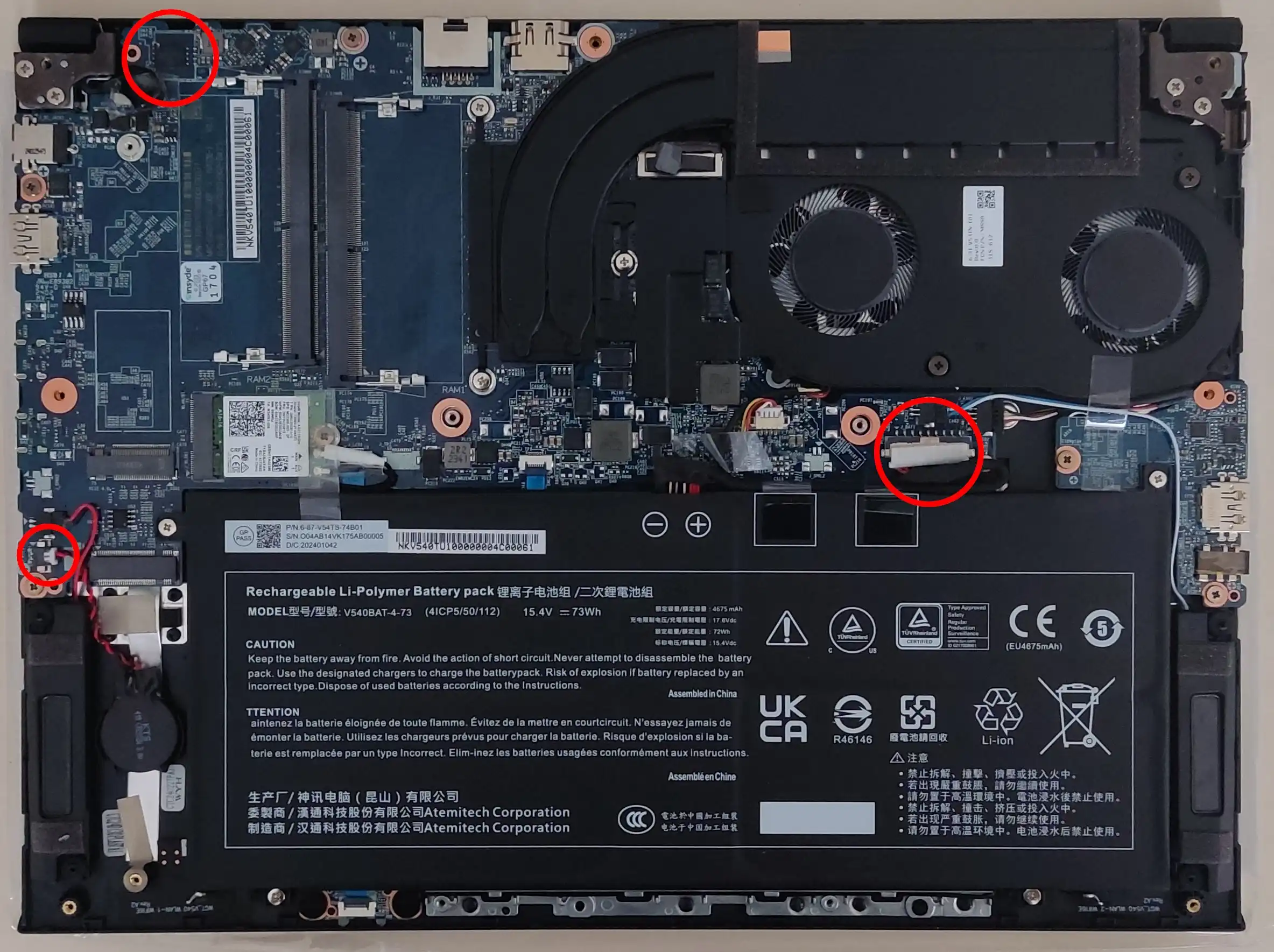
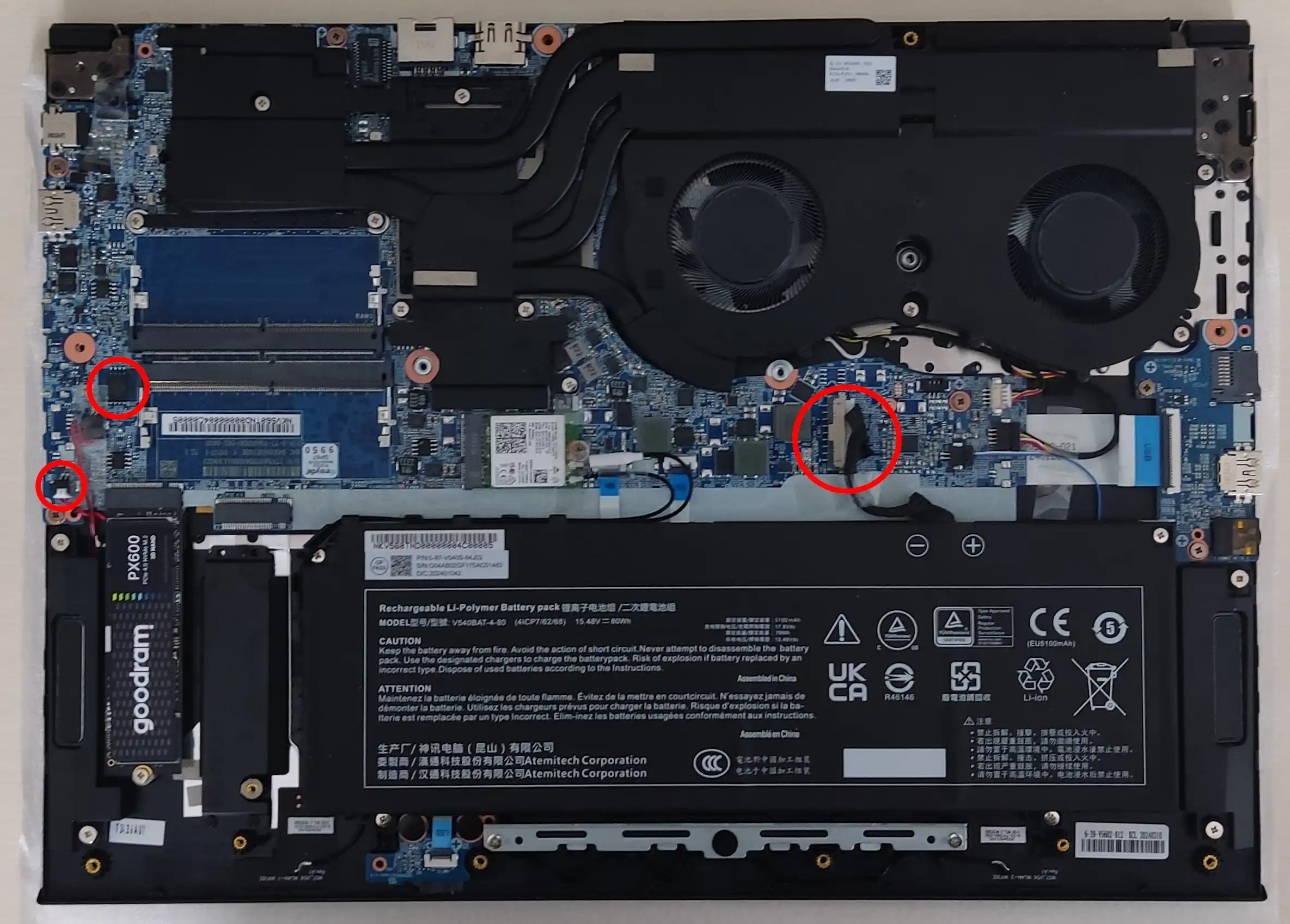
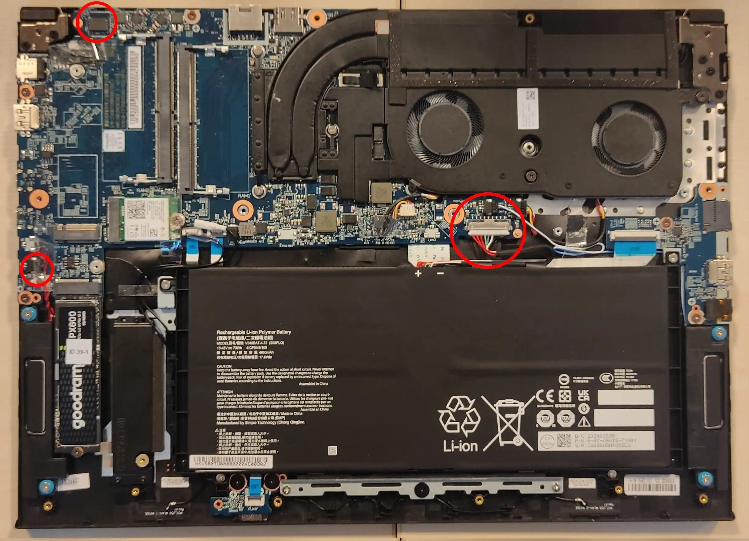
Remove bottom cover from the laptop.
-
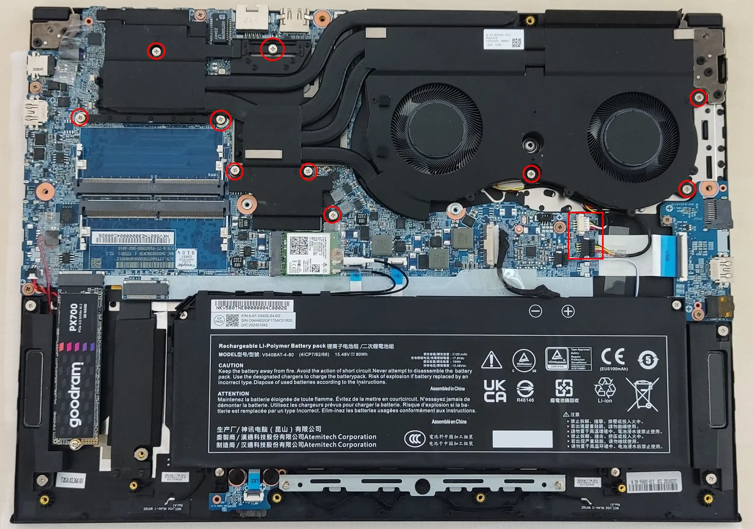
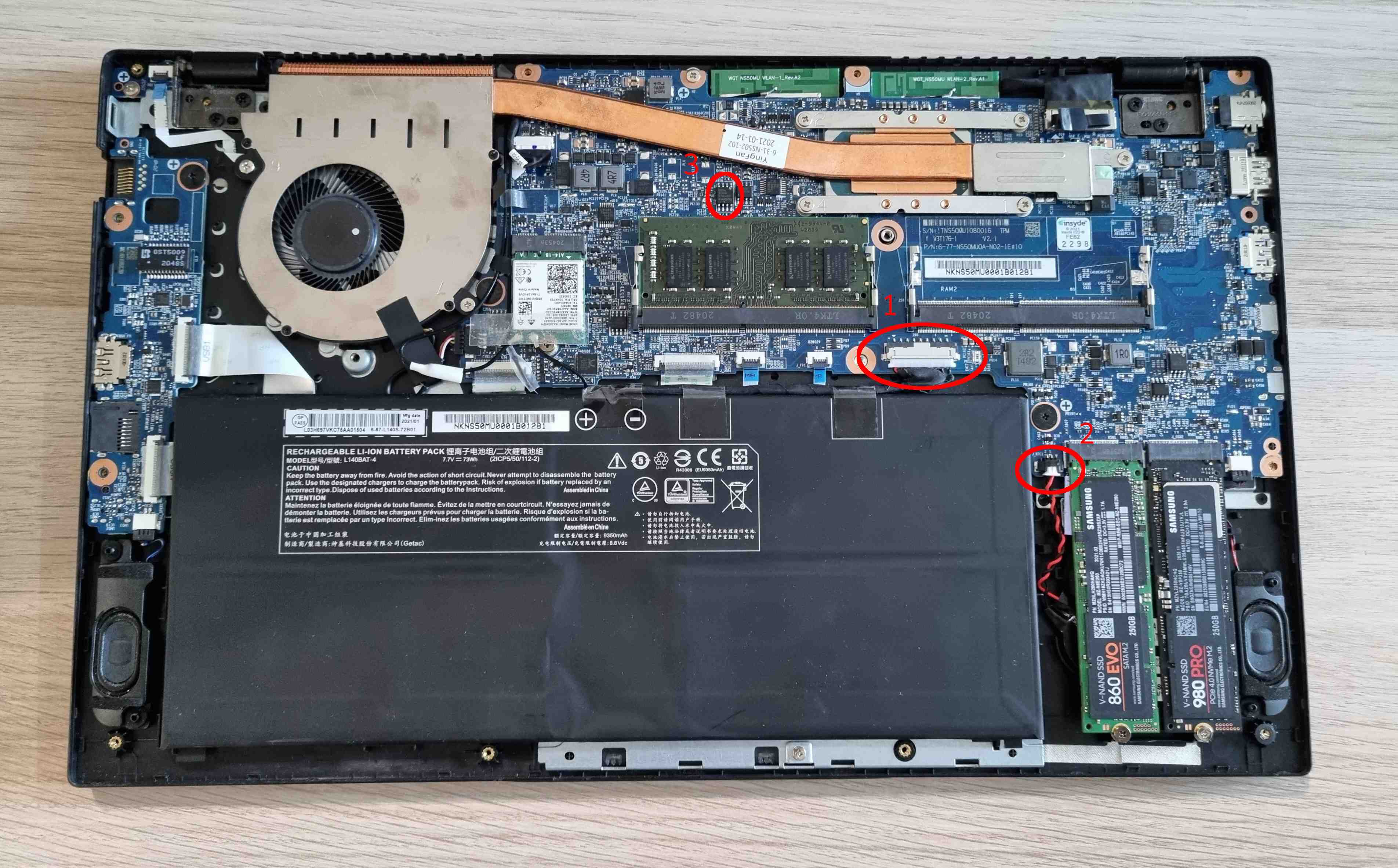
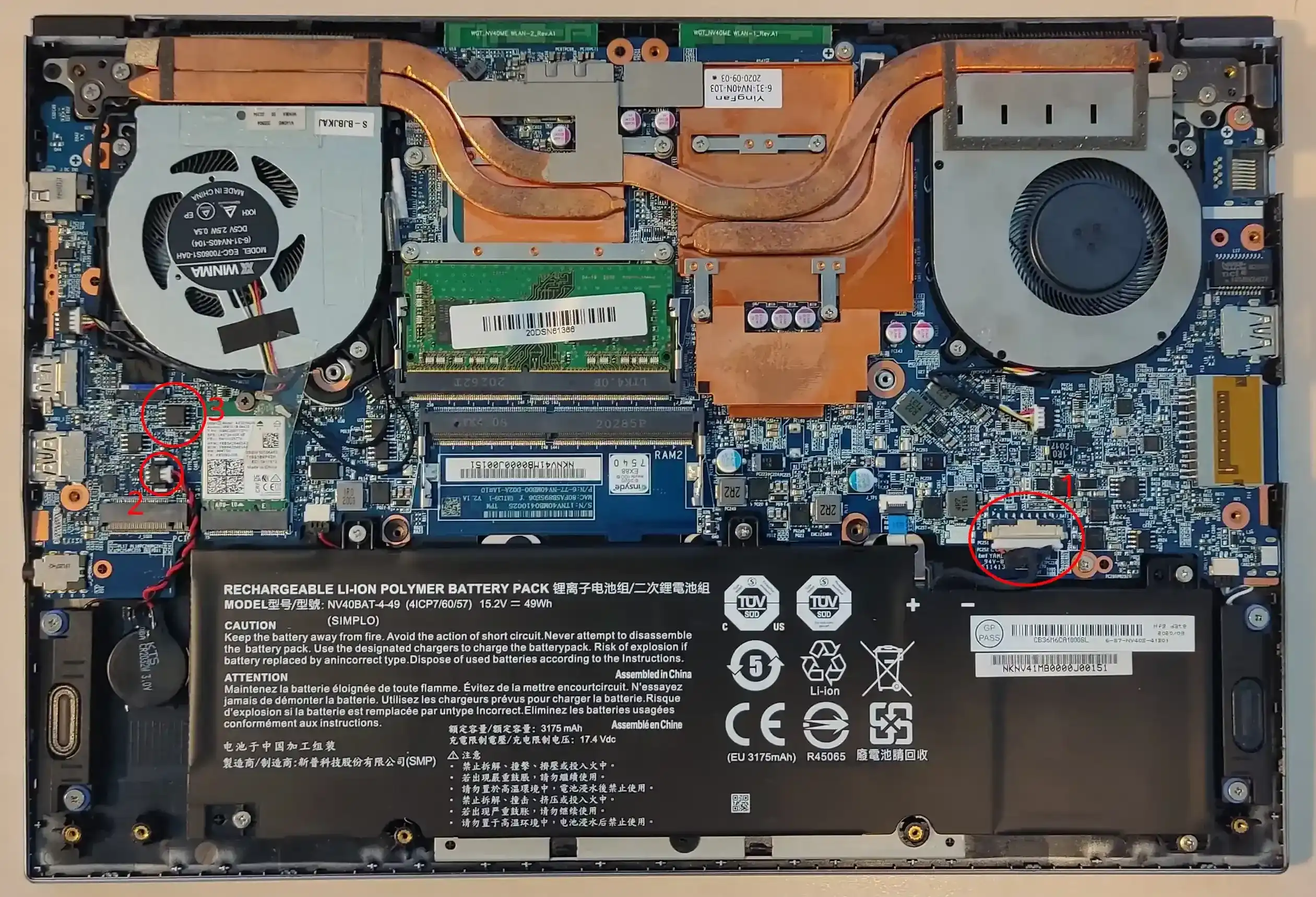
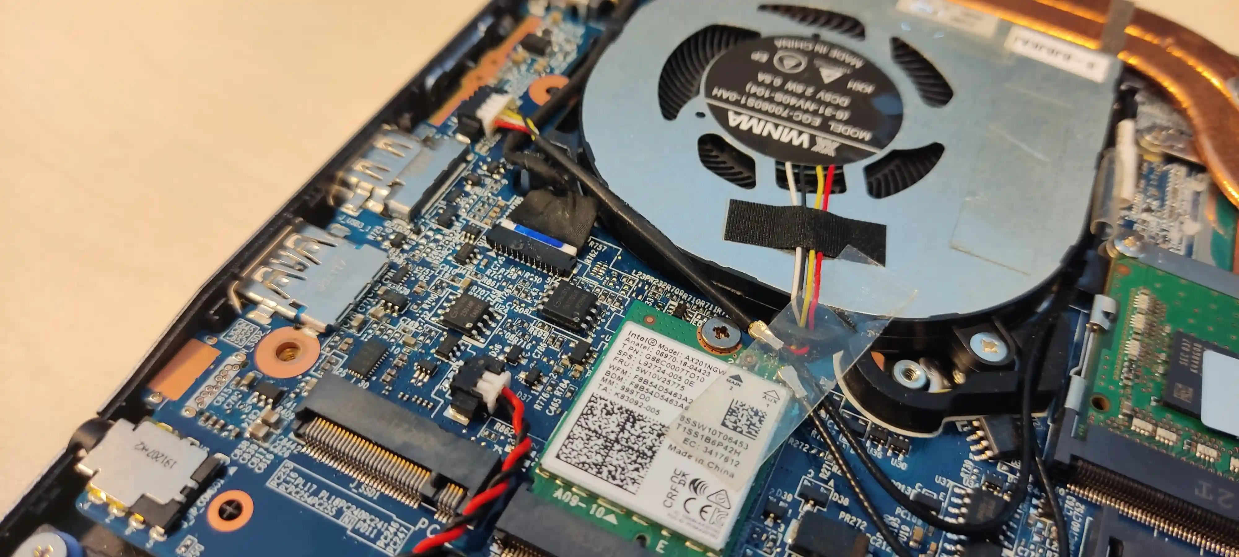
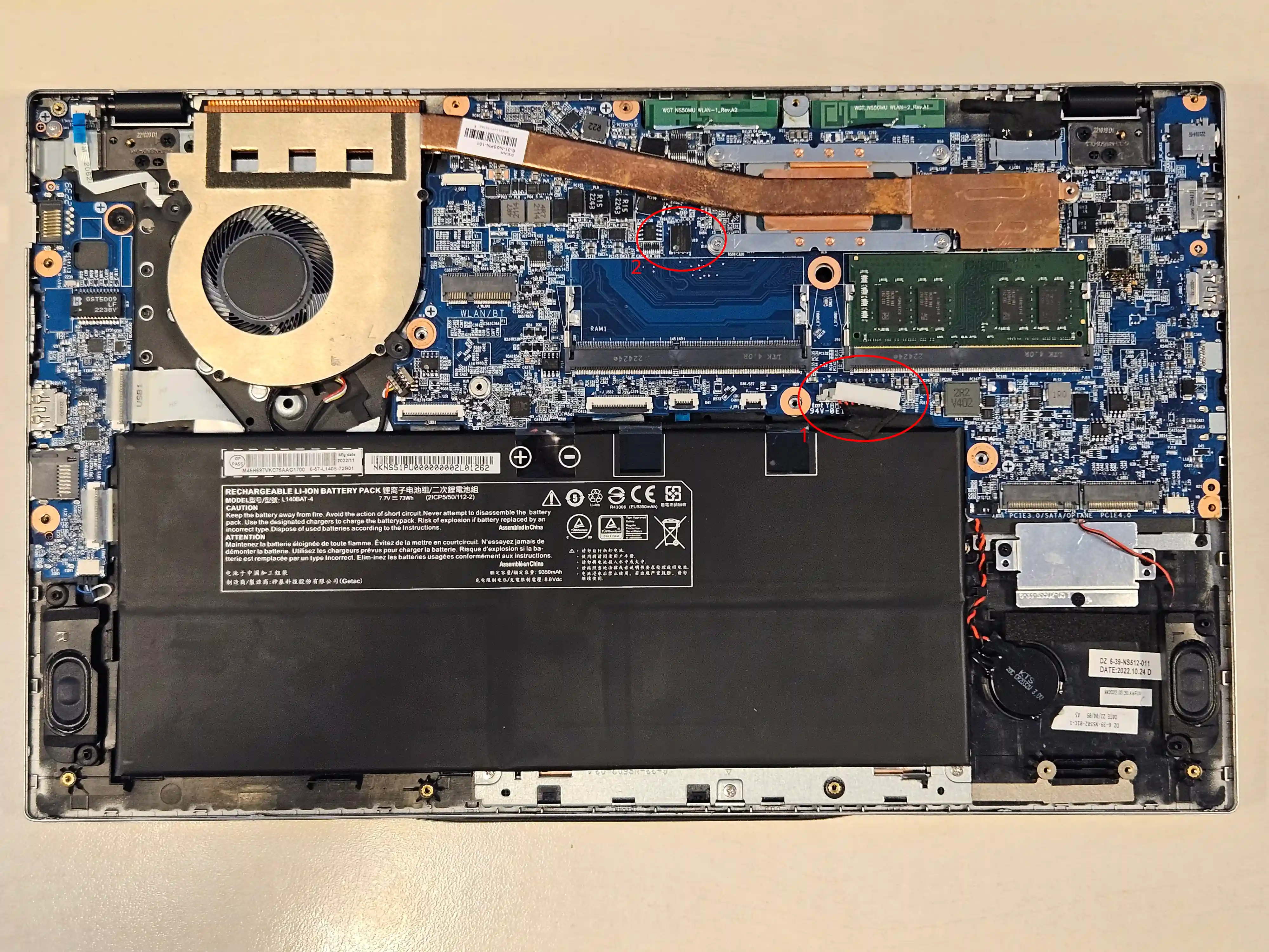
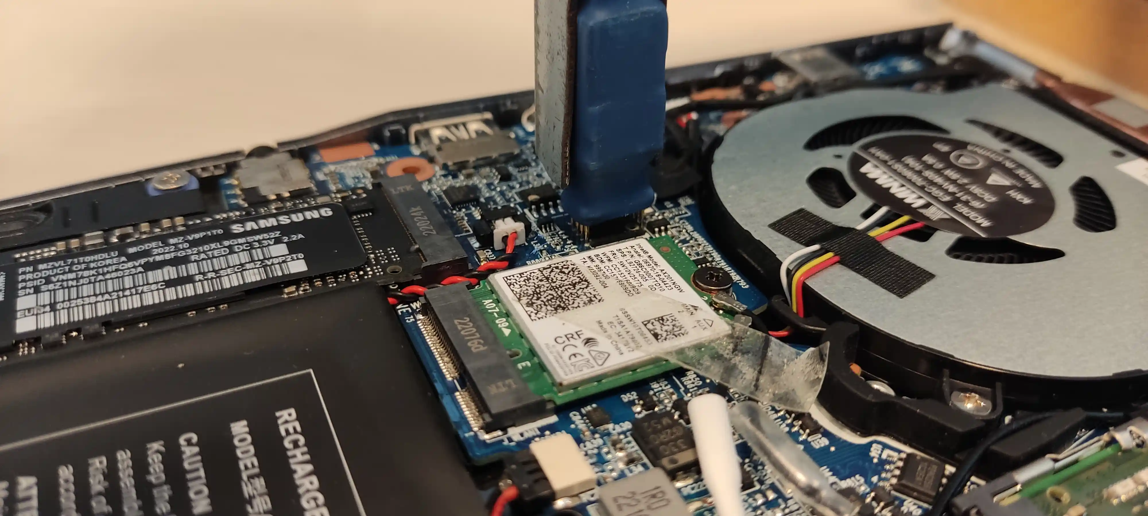
Unplug the battery (1)
Warning
Disconnecting the CMOS battery will result in the internal date being reset.
-
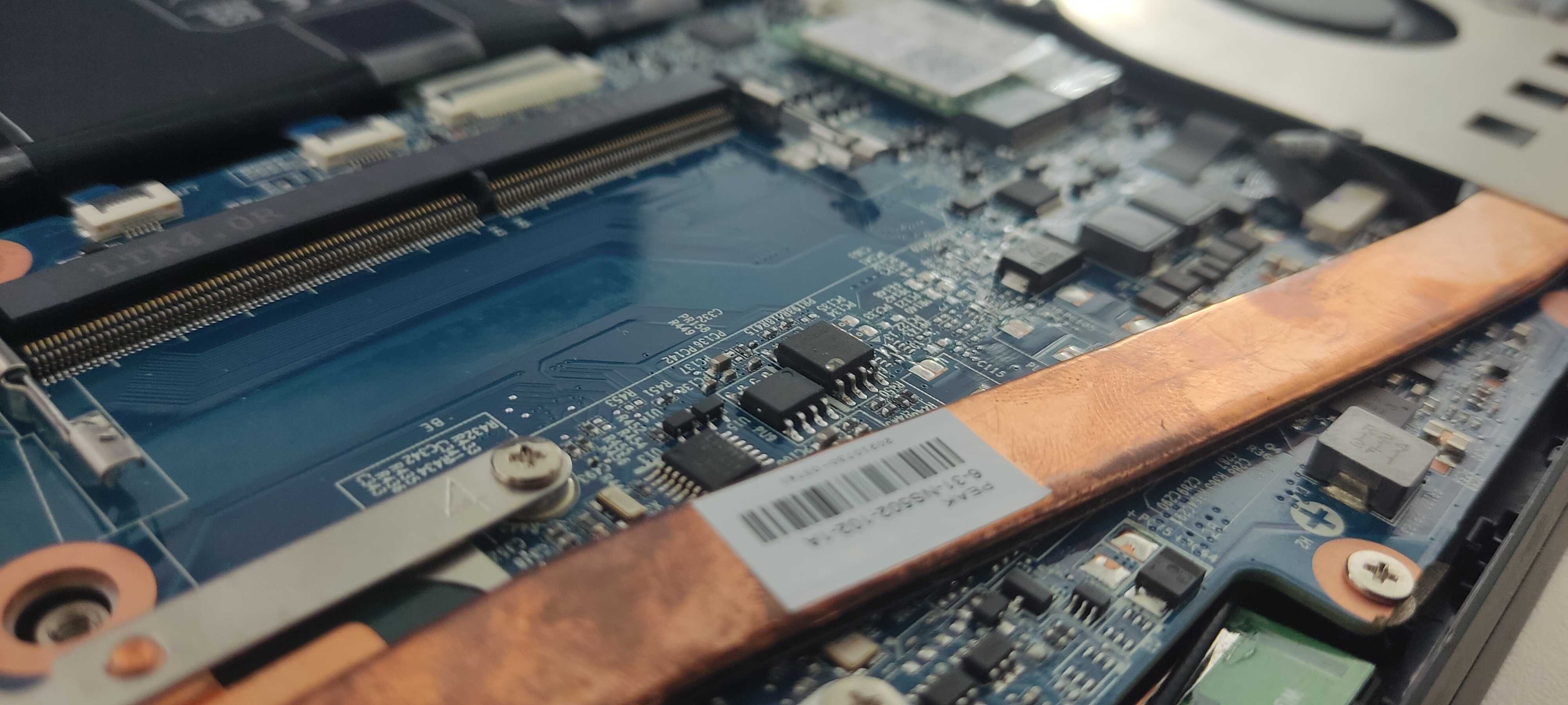
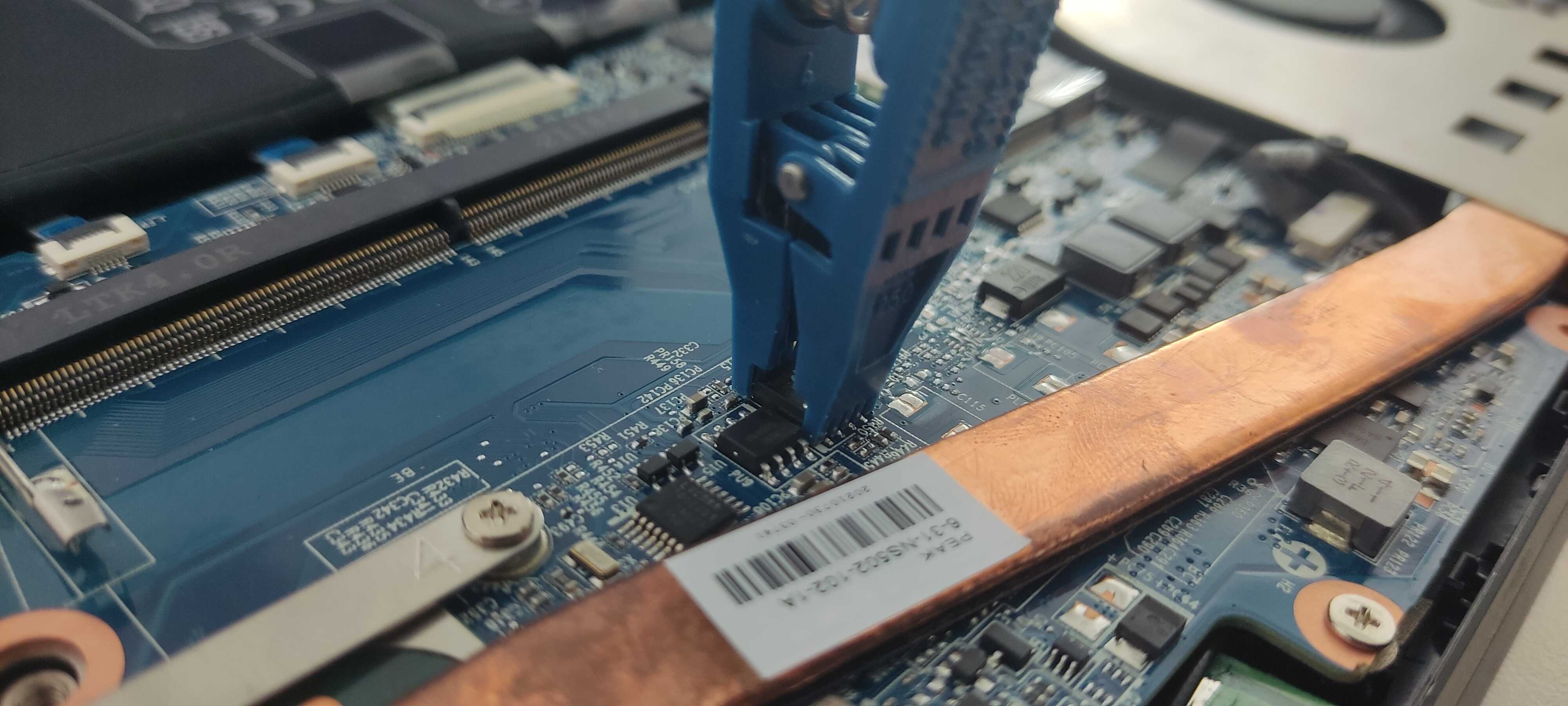
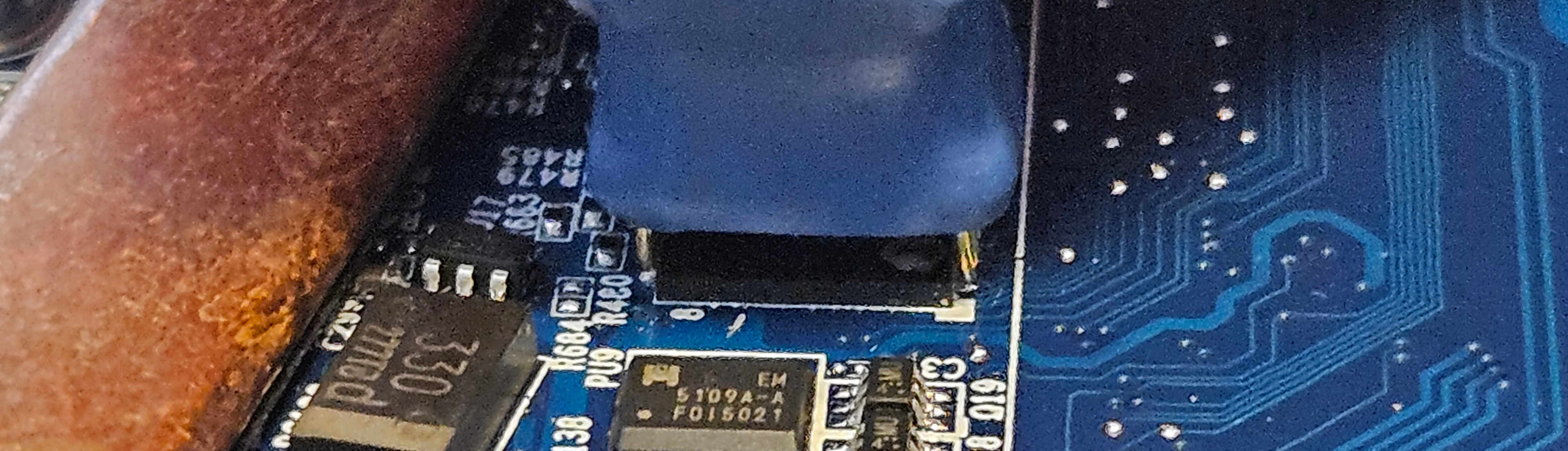
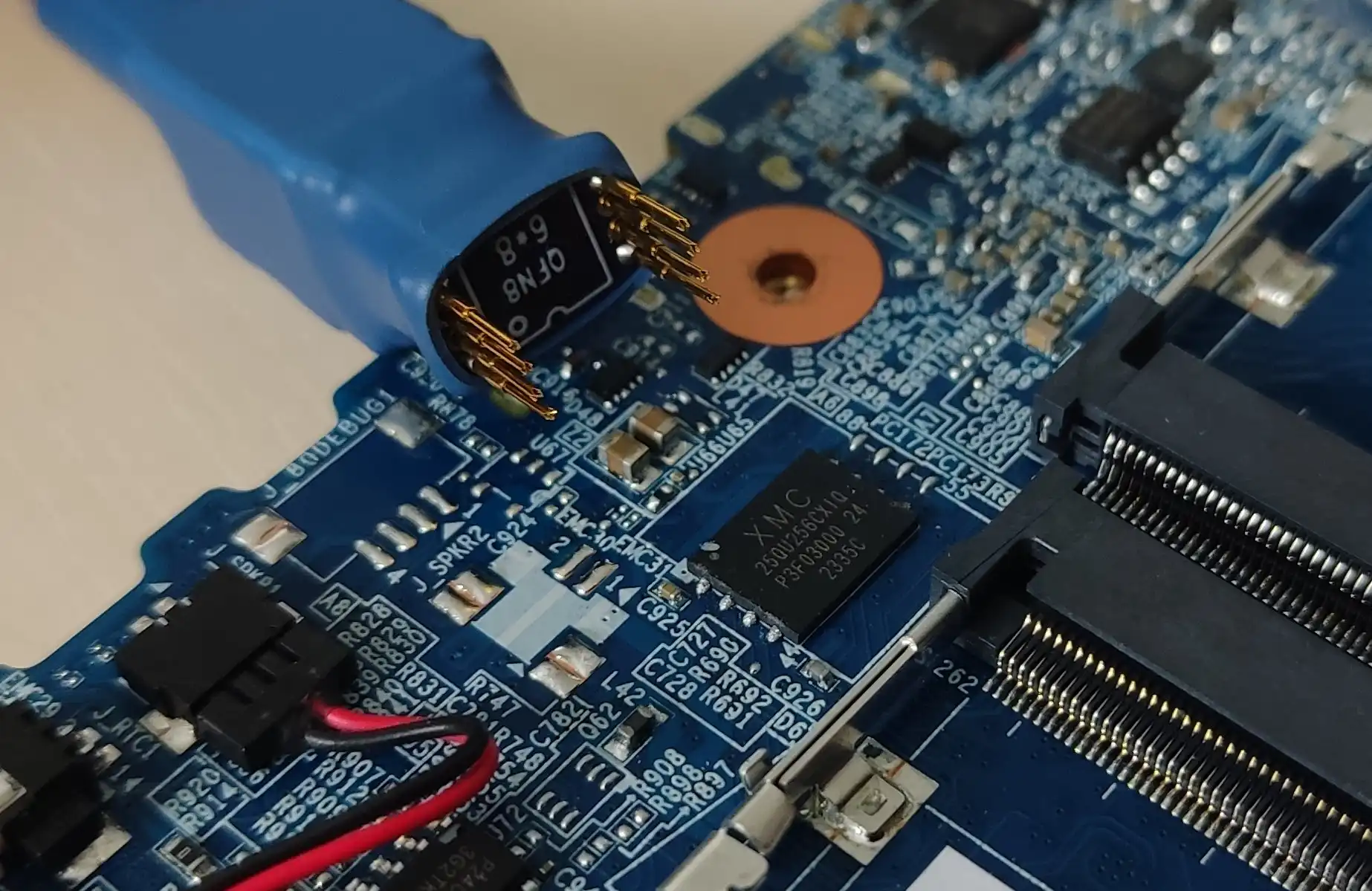
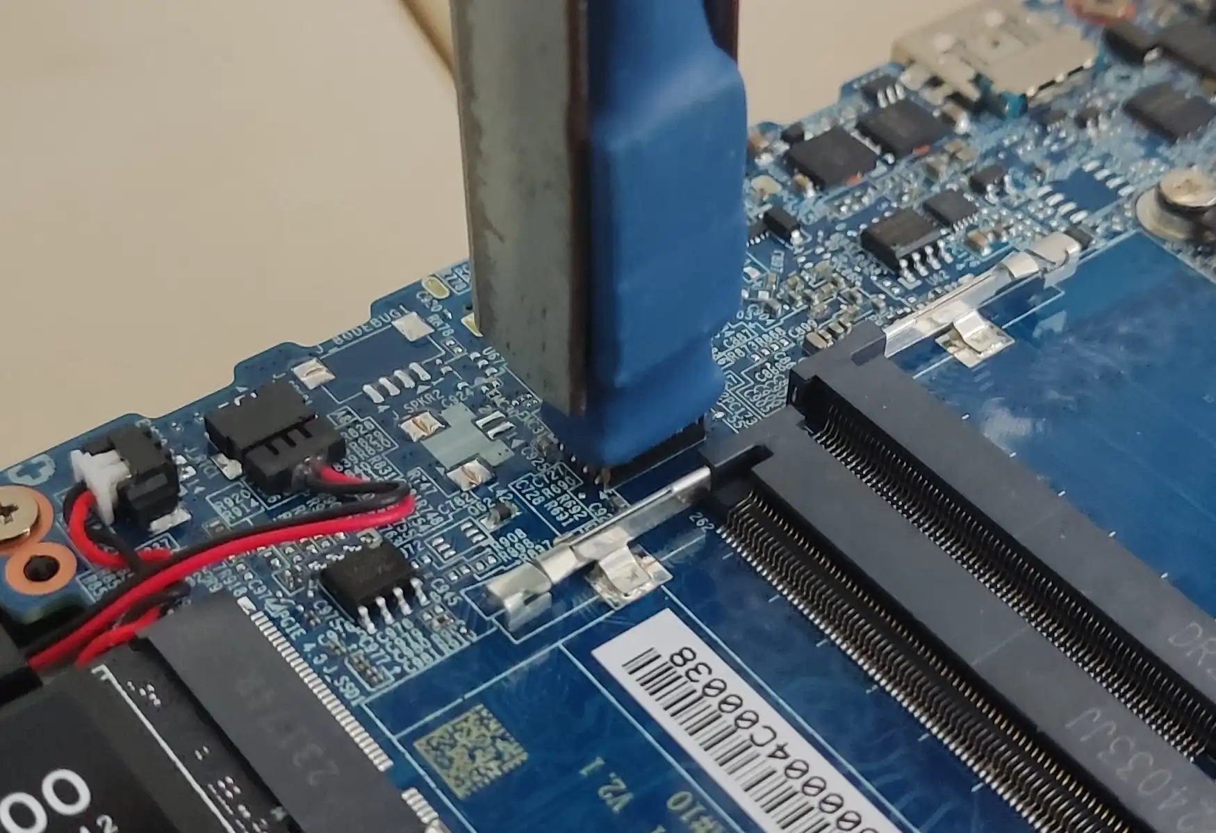
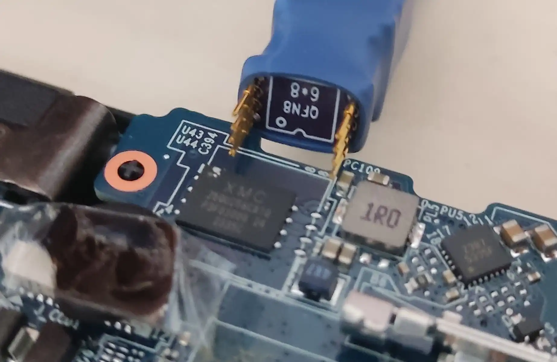
Place the SOIC-8 Pomona clip on the BIOS chip, taking care to align the CS pin with the white dot on the BIOS chip:
-
Attach the SOIC-8 Pomona clip firmly in place and execute the following command on your host computer:
sudo flashrom -p ch341a_spi -w path/to/firmware.bin -
Power on the laptop to verify the recovery passed. First boot may take a while, so be patient.
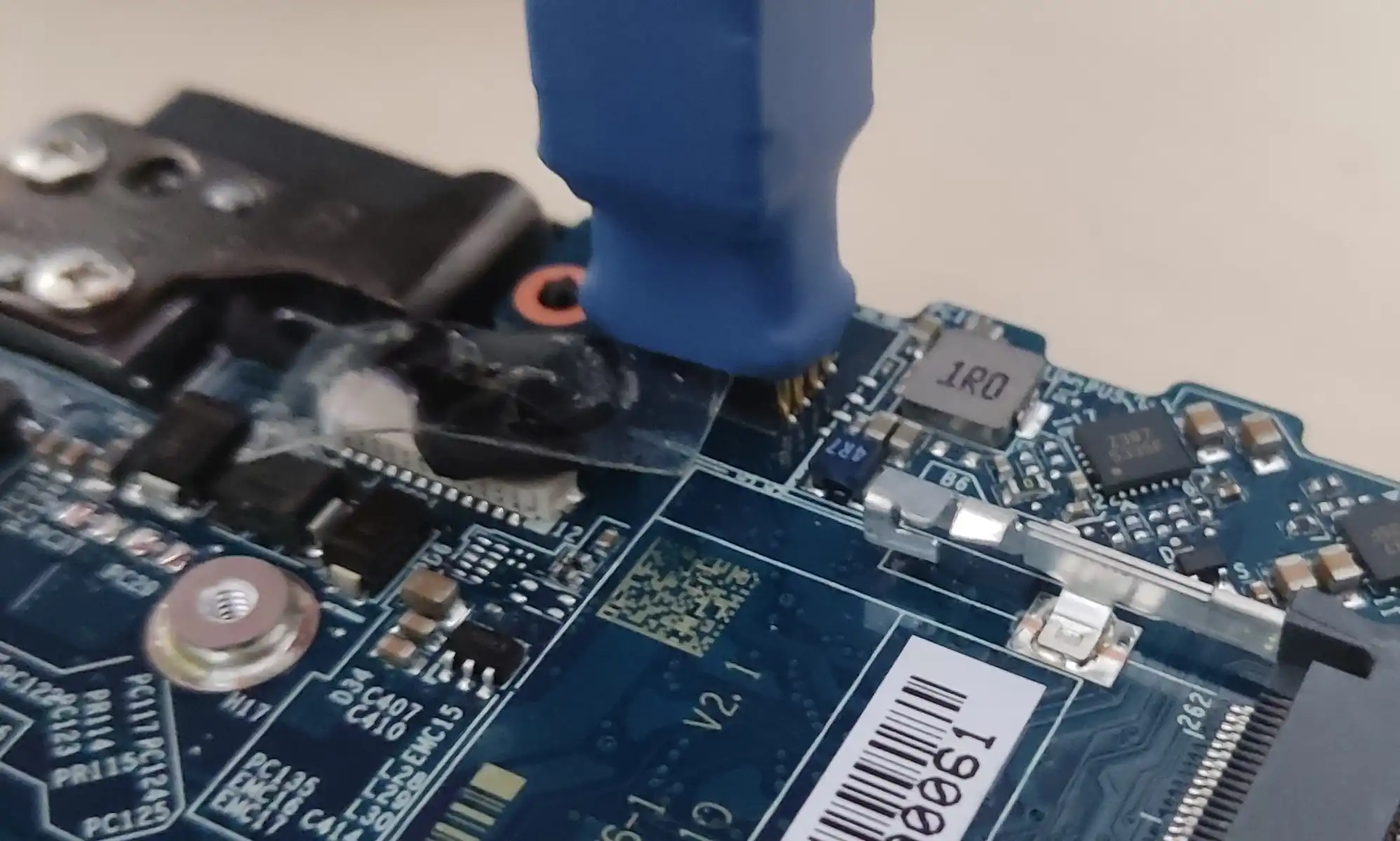
-
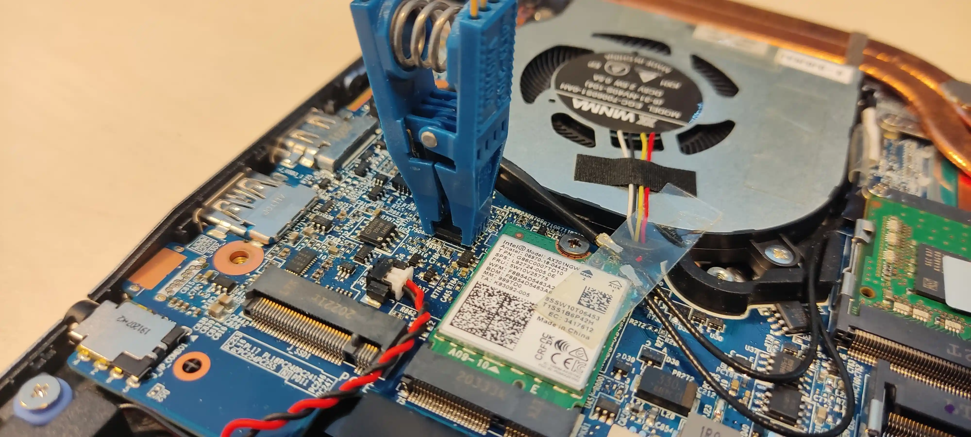
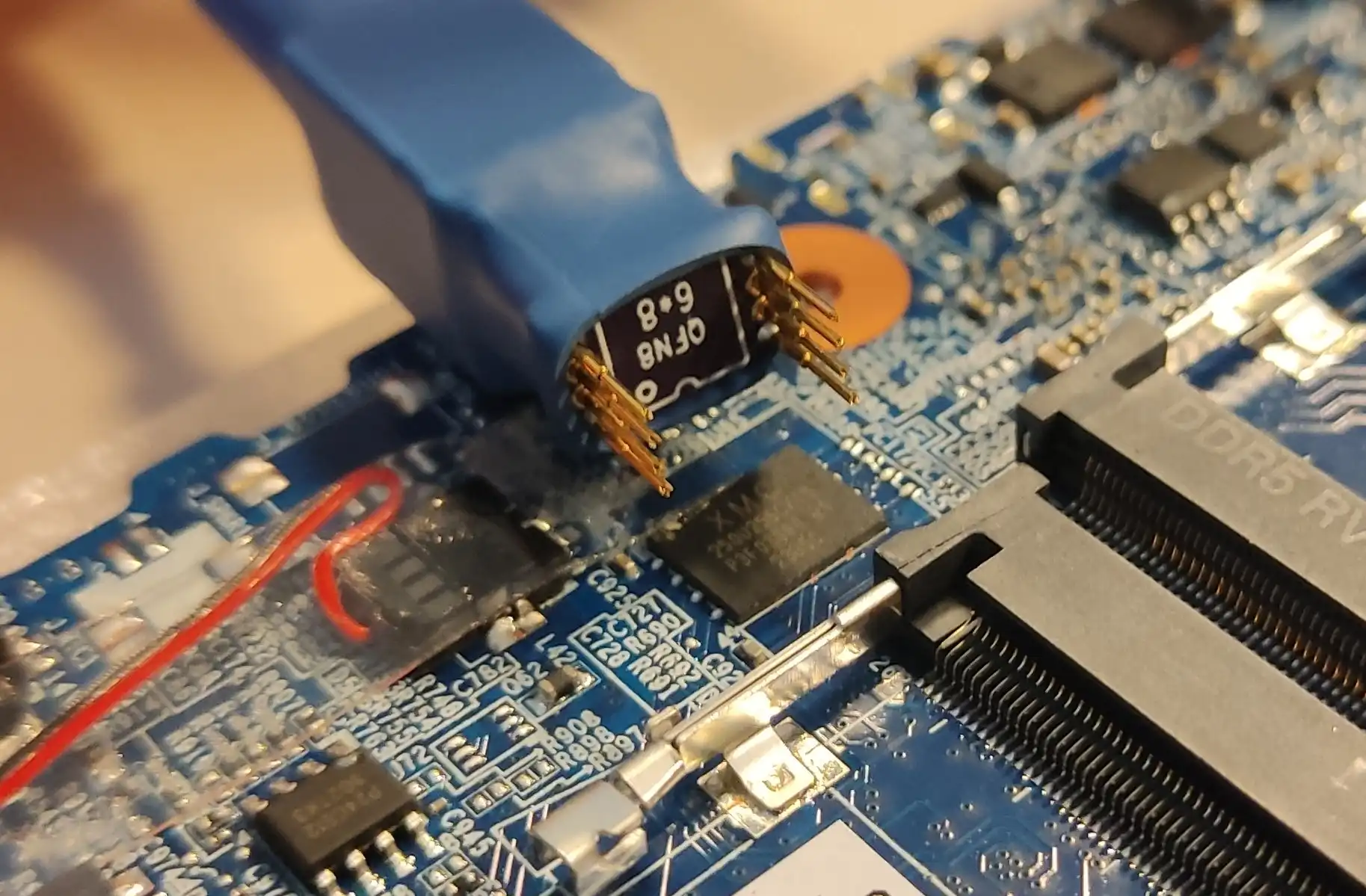
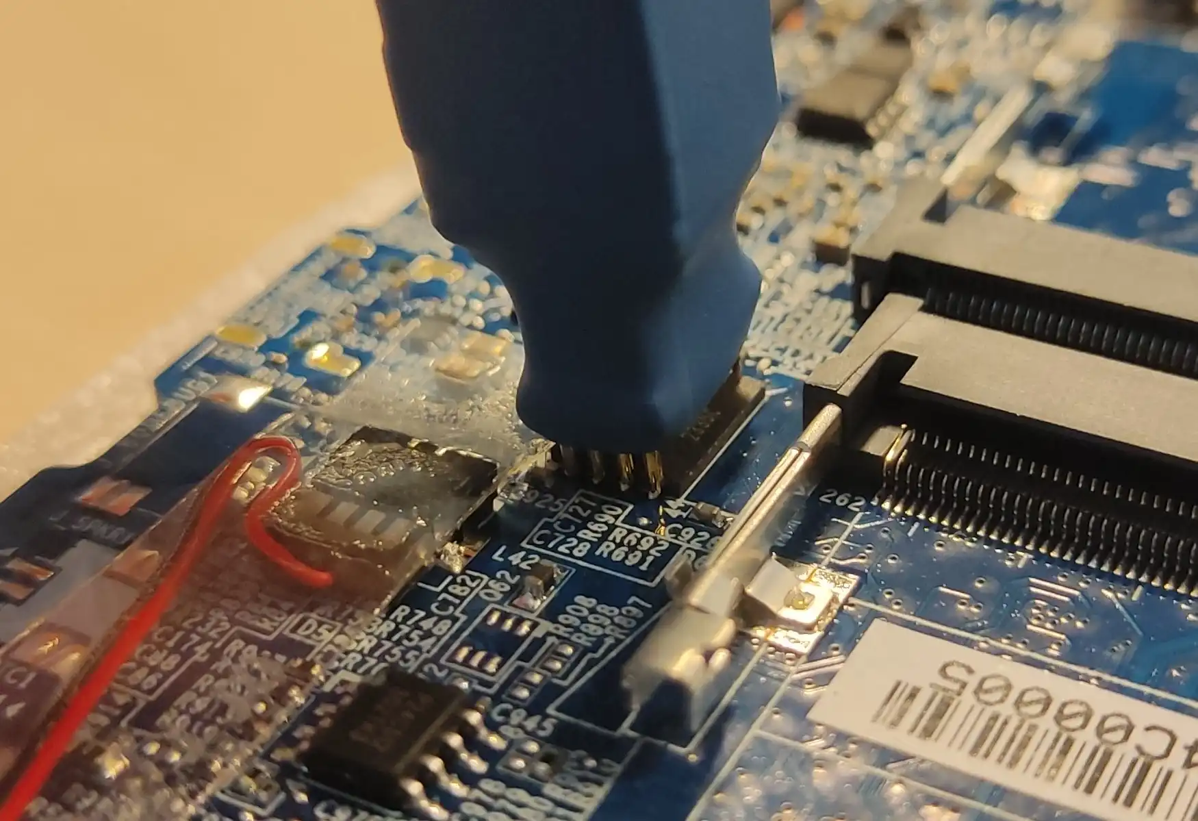
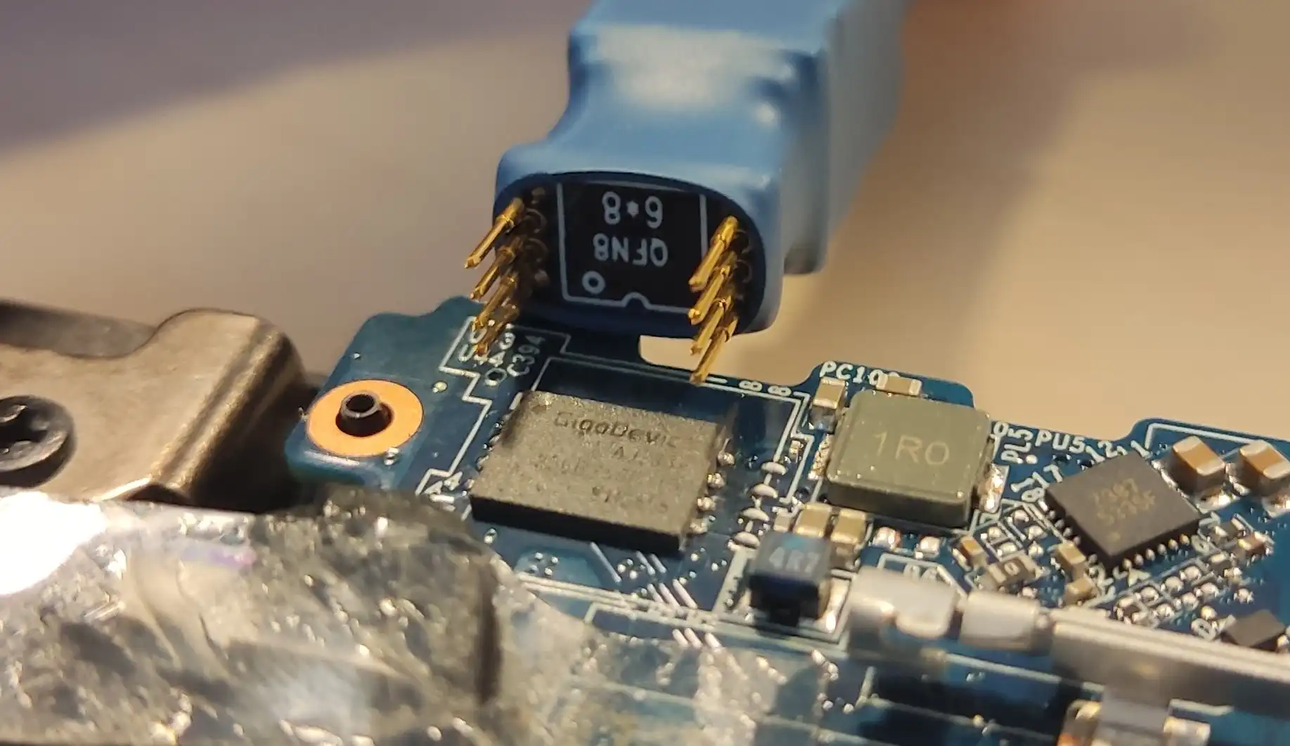
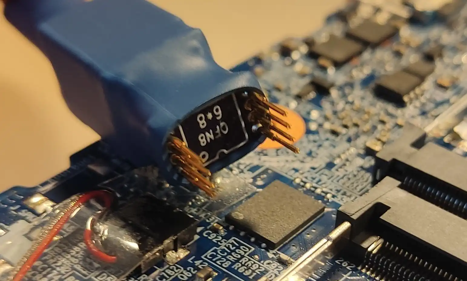
Attach the WSON probe to the programmer. Take care to align pin 1 indicated on the probe's breakout board with pin 1 on the programmer:
Danger
If your CH341a programmer has a voltage switch, make sure it's at 3.3V. Improper voltage selection may result in hardware damage.
-
Plug the programmer into your host computer.
-
Remove bottom cover from the laptop.

-
Unplug the battery (1)
Warning
Disconnecting the CMOS battery will result in the internal date being reset.
-
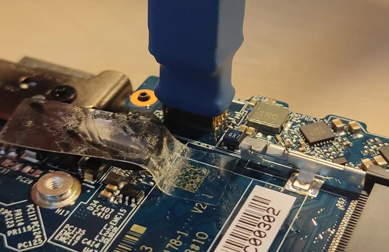
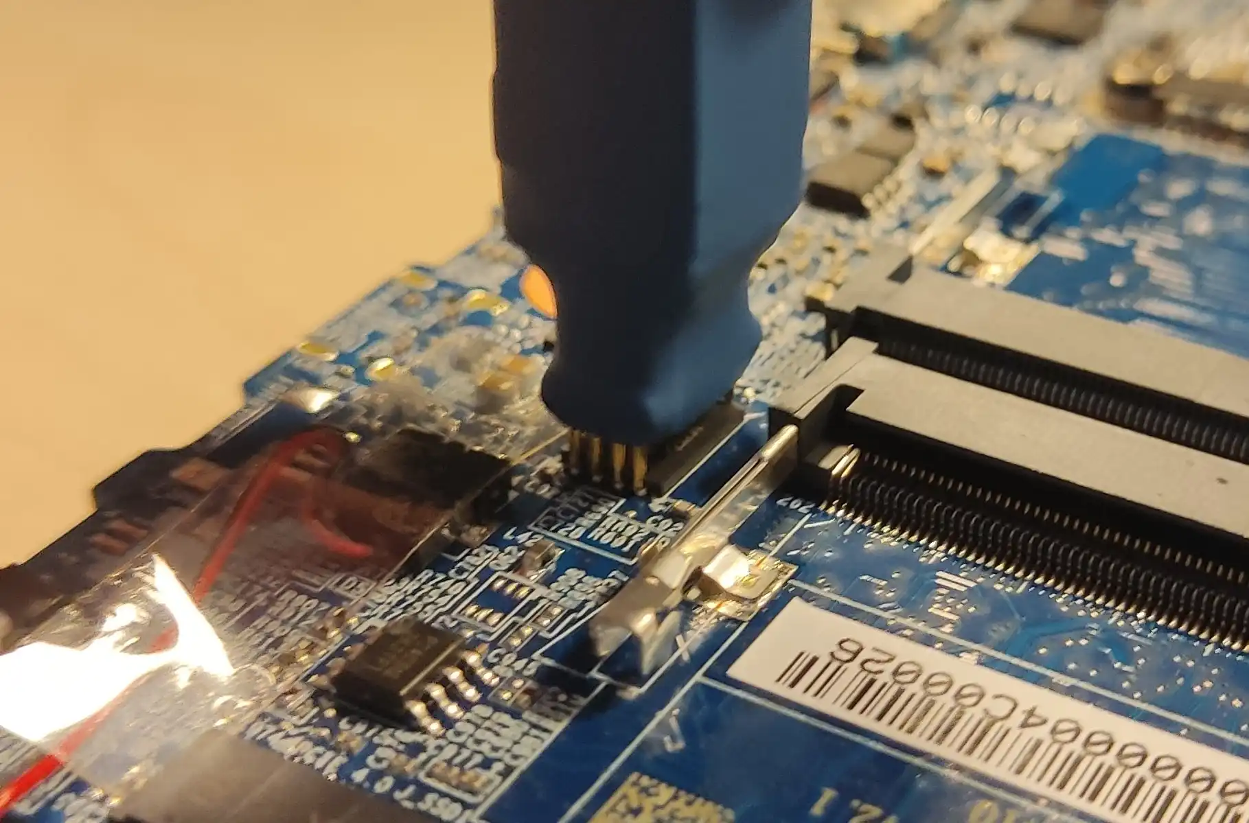
Place the WSON probe on the BIOS chip, taking care to align the dot on the WSON probe with the white dot on the BIOS chip:

-
Hold down the WSON probe firmly in place and execute the following command on your host computer:
sudo flashrom -p ch341a_spi -w path/to/firmware.bin -
Power on the laptop to verify the recovery passed. First boot may take a while, so be patient.
-
Attach the WSON probe to the programmer. Take care to align pin 1 indicated on the probe's breakout board with pin 1 on the programmer:
Danger
If your CH341a programmer has a voltage switch, make sure it's at 1.8V. Improper voltage selection may result in hardware damage.
-
Plug the programmer into your host computer.
-
Remove bottom cover from the laptop.
-
Unplug the battery (1)
Warning
Disconnecting the CMOS battery will result in the internal date being reset.
-
Place the WSON probe on the BIOS chip, taking care to align the dot on the WSON probe with the white dot on the BIOS chip:
-
Hold down the WSON probe firmly in place and execute the following commands on your host computer:
sudo flashrom -p ch341a_spi --ifd -i fd -w [backup.bin] && \
sudo flashrom -p ch341a_spi --ifd -i me -i bios -w [backup.bin]
Note: The commands will first flash FD region, followed by ME and BIOS regions. The reason is all regions are FD dependent, therefore, it must be ensured the FD gets flashed first.
-
Power on the laptop to verify the recovery passed. First boot may take a while, so be patient.
Troubleshooting
If the device is not booting, despite following these instructions, follow the troubleshooting steps below:
Replace the ram modules
Try replacing the RAM modules and booting again.
CMOS Reset
Try performing a CMOS reset:
-
Disconnect the power supply
-
Disconnect the system battery and the CMOS battery
-
Press the power button repeatedly to discharge any remaining charge
-
Leave the laptop disconnected from power for one minute
-
Plug everything back in and power on the laptop
Flash erase + CMOS reset
Try to boot the laptop with the flash erased once, and perform a CMOS reset:
- Using flashrom, erase the entire flash chip:
sudo flashrom -p ch341a_spi --erase
-
Power on the laptop
-
Disconnect the system battery and the CMOS battery
-
Leave the laptop disconnected from power for one minute
-
Flash the correct firmware for the platform
sudo flashrom -p ch341a_spi -w path/to/firmware.bin
- Plug everything back in and power on the laptop
The NovaCustom NUC BOX-155H platform utilizes a socket-mounted WSON8 flash memory device to store its system firmware. Owing to the package's lack of exposed signal pins, conventional in-circuit programming tools such as Pomona clips are inapplicable. Instead, firmware provisioning must occur via physical extraction and external reprogramming of the WSON8 module.
⚠️ Caution: The mechanical tolerances of the socket and the fragility of the chip necessitate careful handling. Excessive insertions and removals may result in socket fatigue or irreversible damage to the flash device. This procedure is inherently manual and is ill-suited for deployment in automated or continuous integration workflows.
Required Equipment and Software Dependencies
| Component | Functionality Description |
|---|---|
| CH341A USB SPI Programmer | Facilitates external SPI flash interfacing and programming |
| WSON8-to-SOIC8 Adapter | Converts the WSON8 package to a pin-compatible SOIC8 form factor for programmer compatibility |
| Validated Firmware Binary | Target image to be written to the flash device |
flashrom Utility |
Cross-platform, command-line tool for direct SPI flash manipulation |
Firmware Restoration Protocol
-
Ensure the NUC BOX-155H is fully powered down and disconnected from all electrical sources.
-
Employ ESD-safe tools to carefully extract the WSON8 flash chip from its socketed interface.
-
Insert the chip into the WSON8-to-SOIC8 adapter, ensuring correct pin-1 orientation based on device markings.
-
Mount the adapter into the CH341A programmer and connect it to the host workstation via USB.
-
Execute the flashing sequence using the following command:
flashrom -p ch341a_spi -w /path/to/firmware.bin
-
Upon successful write verification, detach the chip from the programming assembly and reinstall it into the motherboard socket, verifying alignment and insertion depth.
-
Reconnect the power supply and other system interfaces, and initiate a power-on cycle.
-
Be advised that initial boot time may be extended as the platform performs low-level firmware initialization routines.
Following this procedure, the system should transition into normal operational state.