SPI hardware write protection
In order to from a Root of Trust in the firmware, e.g. in the immutable piece of firmware code for Static Root of Trust of Measurement one has to ensure the protection of this piece of code. One may achieve it by enabling Intel Boot Guard or AMD Platform Secure Boot. However these technologies may into always be available. In such case SPI hardware write protection becomes handy.
Thanks to the patchset implementing write protection and OTP support in flashrom one can easily set the SPI write protection of the platform from the operating system user space. This page explain how to build the flashrom with WP and OTP support and use to to protect the coreboot's bootblock to form SRTM.
Building flashrom
In order to build flashrom we will need some packages and librares. For Debian based distros execute:
sudo apt-get install git make binutils build-essential ca-certificates \
             libpci-dev libftdi-dev libusb-1.0-0-dev
Now clone the flashrom repository and fetch the patchset:
git clone https://github.com/flashrom/flashrom
cd flashrom
git fetch https://review.coreboot.org/flashrom refs/changes/13/59713/7 && \
    git checkout FETCH_HEAD
Build flashrom:
make
The freshly built flashrom will be present in root directory of the repository.
Flashrom write protection CLI
Invoke the following command to see a list of available options for flashrom:
./flashrom --help
flashrom v1.2-585-g3542afe on Linux 5.10.0-9-amd64 (x86_64)
flashrom is free software, get the source code at https://flashrom.org

Usage: ./flashrom [-h|-R|-L|
    -p <programmername>[:<parameters>] [-c <chipname>]
        (--flash-name|--flash-size|
         [-E|-x|(-r|-w|-v) <file>]
         [(-l <layoutfile>|--ifd| --fmap|--fmap-file <file>) [-i <region>[:<file>]]...]
         [-n] [-N] [-f])]
    [-V[V[V]]] [-o <logfile>]

 -h | --help                        print this help text
 -R | --version                     print version (release)
 -r | --read <file>                 read flash and save to <file>
 -w | --write <file|->              write <file> or the content provided
                                    on the standard input to flash
 -v | --verify <file|->             verify flash against <file>
                                    or the content provided on the standard input
 -E | --erase                       erase flash memory
 -V | --verbose                     more verbose output
 -c | --chip <chipname>             probe only for specified flash chip
 -f | --force                       force specific operations (see man page)
 -n | --noverify                    don't auto-verify
 -N | --noverify-all                verify included regions only (cf. -i)
 -x | --extract                     extract regions to files
 -l | --layout <layoutfile>         read ROM layout from <layoutfile>
      --wp-disable                  disable write protection
      --wp-enable                   enable write protection
      --wp-list                     list supported write protection ranges
      --wp-status                   show write protection status
      --wp-range=<start>,<len>      set write protection range (use --wp-range=0,0
                                    to unprotect the entire flash)
      --wp-region <region>          set write protection region
      --otp-status                  print information about OTP regions
      --otp-region <otp-region>     OTP region number (base 1) to operate on
      --otp-read <file>             read OTP region and save it to <file>
      --otp-write <file>            write <file> to OTP region
      --otp-erase                   erase OTP region
      --otp-lock                    lock OTP region
      --flash-name                  read out the detected flash name
      --flash-size                  read out the detected flash size
      --fmap                        read ROM layout from fmap embedded in ROM
      --fmap-file <fmapfile>        read ROM layout from fmap in <fmapfile>
      --ifd                         read layout from an Intel Firmware Descriptor
 -i | --image <region>[:<file>]     only read/write image <region> from layout
                                    (optionally with data from <file>)
 -o | --output <logfile>            log output to <logfile>
      --flash-contents <ref-file>   assume flash contents to be <ref-file>
 -L | --list-supported              print supported devices
 -p | --programmer <name>[:<param>] specify the programmer device. One of
    internal, dummy, nic3com, nicrealtek, gfxnvidia, raiden_debug_spi, drkaiser,
    satasii, atavia, it8212, ft2232_spi, serprog, buspirate_spi, dediprog,
    developerbox, rayer_spi, pony_spi, nicintel, nicintel_spi, nicintel_eeprom,
    ogp_spi, satamv, linux_mtd, linux_spi, usbblaster_spi, pickit2_spi,
    ch341a_spi, digilent_spi, stlinkv3_spi.

You can specify one of -h, -R, -L, -E, -r, -w, -v or no operation.
If no operation is specified, flashrom will only probe for flash chips.
We will use only a few of those options to set the protection on the coreboot's bootblock. We protect the bootblock only, since it is the stage responsible for measurements and verification of next stages.
Setting flash protection using flashrom
NOTE: be sure to update the firmware first before proceeding!
Estimating bootblock size and protection range
First let's see how much space we need to protect. Take your coreboot.rom file and use cbfstool to show its contents:
cd /path/to/coreboot/build
./cbfstool coreboot.rom print
FMAP REGION: COREBOOT
Name                           Offset     Type           Size   Comp
cbfs master header             0x0        cbfs header        32 none
fallback/romstage              0x80       stage          171040 none
fallback/ramstage              0x29d40    stage           98703 LZMA (229532 decompressed)
config                         0x41f40    raw               709 none
revision                       0x42240    raw               723 none
build_info                     0x42540    raw               101 none
fallback/dsdt.aml              0x42600    raw              7055 none
cmos.default                   0x441c0    cmos_default      256 none
cmos_layout.bin                0x44300    cmos_layout      3676 none
fallback/postcar               0x451c0    stage           21216 none
img/nvramcui                   0x4a500    simple elf      70630 none
fallback/payload               0x5b940    simple elf      69936 none
payload_config                 0x6cac0    raw              1621 none
payload_revision               0x6d140    raw               237 none
pci8086,10d3.rom               0x6d280    raw             82944 none
etc/sercon-port                0x816c0    raw                 8 none
(empty)                        0x81700    null          8128932 none
bootblock                      0xffcac0   bootblock       13056 none
The bootblock is taking slightly more than 12KB of space on the bottom of the
flash. Converting 12KB to hex would be equal to 0x3000 but we must cover a
little bit more than that. Let's see what protection ranges are available for
the chip (running from the target machine to be protected):
./flashrom -p internal --wp-list
...
Available write protection ranges:
    start=0x00000000 length=0x00000000 (none)
    start=0x00000000 length=0x00001000 (lower 1/2048)
    start=0x007ff000 length=0x00001000 (upper 1/2048)
    start=0x00000000 length=0x00002000 (lower 1/1024)
    start=0x007fe000 length=0x00002000 (upper 1/1024)
    start=0x00000000 length=0x00004000 (lower 1/512)
    start=0x007fc000 length=0x00004000 (upper 1/512)
    start=0x00000000 length=0x00008000 (lower 1/256)
    start=0x007f8000 length=0x00008000 (upper 1/256)
    start=0x00000000 length=0x00020000 (lower 1/64)
    start=0x007e0000 length=0x00020000 (upper 1/64)
    start=0x00000000 length=0x00040000 (lower 1/32)
    start=0x007c0000 length=0x00040000 (upper 1/32)
    start=0x00000000 length=0x00080000 (lower 1/16)
    start=0x00780000 length=0x00080000 (upper 1/16)
    start=0x00000000 length=0x00100000 (lower 1/8)
    start=0x00700000 length=0x00100000 (upper 1/8)
    start=0x00000000 length=0x00200000 (lower 1/4)
    start=0x00600000 length=0x00200000 (upper 1/4)
    start=0x00000000 length=0x00400000 (lower 1/2)
    start=0x00400000 length=0x00400000 (upper 1/2)
    start=0x00000000 length=0x00600000 (lower 3/4)
    start=0x00200000 length=0x00600000 (upper 3/4)
    start=0x00000000 length=0x00700000 (lower 7/8)
    start=0x00100000 length=0x00700000 (upper 7/8)
    start=0x00000000 length=0x00780000 (lower 15/16)
    start=0x00080000 length=0x00780000 (upper 15/16)
    start=0x00000000 length=0x007c0000 (lower 31/32)
    start=0x00040000 length=0x007c0000 (upper 31/32)
    start=0x00000000 length=0x007e0000 (lower 63/64)
    start=0x00020000 length=0x007e0000 (upper 63/64)
    start=0x00000000 length=0x007f8000 (lower 255/256)
    start=0x00008000 length=0x007f8000 (upper 255/256)
    start=0x00000000 length=0x007fc000 (lower 511/512)
    start=0x00004000 length=0x007fc000 (upper 511/512)
    start=0x00000000 length=0x007fe000 (lower 1023/1024)
    start=0x00002000 length=0x007fe000 (upper 1023/1024)
    start=0x00000000 length=0x007ff000 (lower 2047/2048)
    start=0x00001000 length=0x007ff000 (upper 2047/2048)
    start=0x00000000 length=0x00800000 (all)
The output abvoe comes from Winbond W25Q64FV, a 8MB chip. Bootblock is always
mapped to the bottom of the flash. 1MB is equal to 0x100000 so 8MB would be
0x800000. We need at least 0x4000 (16KB) to be protected starting at the bottom
of the flash. And fortunately we have found our best match:
start=0x007fc000 length=0x00004000 (upper 1/512).
Clearing SPI write protection
Now that we have selected the desired range to protect, it is time to check the current protection status:
./flashrom -p internal --wp-status
...
WP config bits: SRP1=0 SRP0=0 CMP=0 SEC=0 TB=0 BP2=0 BP1=0 BP0=0
Protection range: start=0x00000000 length=0x00000000 (none)
Protection mode: disabled
The protection range should be set to zeros and all WP config bits should be cleared. If you see some bits were not cleared, ensure the WP pin jumper on the flash is not placed and invoke:
./flashrom -p internal --wp-disable
./flashrom -p internal --wp-range=0,0
now that we have a clear state of the flash protection we may proceed with enabling the right range.
Setting protection range
Copy the range base and length and invoke:
./flashrom -p internal --wp-range=0x007fc000,0x00004000
Setting SPI status register protection
Flashrom should report Successfully set the requested protection range.. Now
set the status register protection so the range protection cannot be changed:
./flashrom -p internal --wp-enable
Flashrom should report Successfully set the requested mode..
Verifying SPI write protection
To check whether the settings are desired invoke:
./flashrom -p internal --wp-status
...
WP config bits: SRP1=0 SRP0=1 CMP=0 SEC=1 TB=0 BP2=0 BP1=1 BP0=1
Protection range: start=0x007fc000 length=0x00004000 (upper 1/512)
Protection mode: hardware
If it matches what you have wanted to set it is time to lock the status register protection bit (SRP0) from being changed. SRP0 protects the CMP, SEC, TB and BPx bits from being changed. In order to lock the SRP0 bit you have to place the jumper on the WP pin and tie it to ground (GND). This will assert the WP pin and prevent any WP config bits from being changed. To verify it invoke:
./flashrom -p internal --wp-disable
...
Writing new WP configuration failed during verification:
Expected configuration: SRP1=0 SRP0=0 CMP=0 SEC=1 TB=0 BP2=0 BP1=1 BP0=1
Actual configuration:   SRP1=0 SRP0=1 CMP=0 SEC=1 TB=0 BP2=0 BP1=1 BP0=1
You should get the above result.
Changing the protection range
Now if you want to reprogram the protection range, you need to take off the jumper and invoke:
./flashrom -p internal --wp-disable
Now you should get Successfully set the requested mode. now. Check the WP
status:
WP config bits: SRP1=0 SRP0=0 CMP=0 SEC=1 TB=0 BP2=0 BP1=1 BP0=1
Protection range: start=0x007fc000 length=0x00004000 (upper 1/512)
Protection mode: disabled
It must indicate Protection mode: disabled. Now you may reconfigure the
range, e.g.
./flashrom -p internal --wp-range=0x007e0000,0x00020000
And proceed with enabling protection and setting back the jumper.
Setting flash protection for vboot
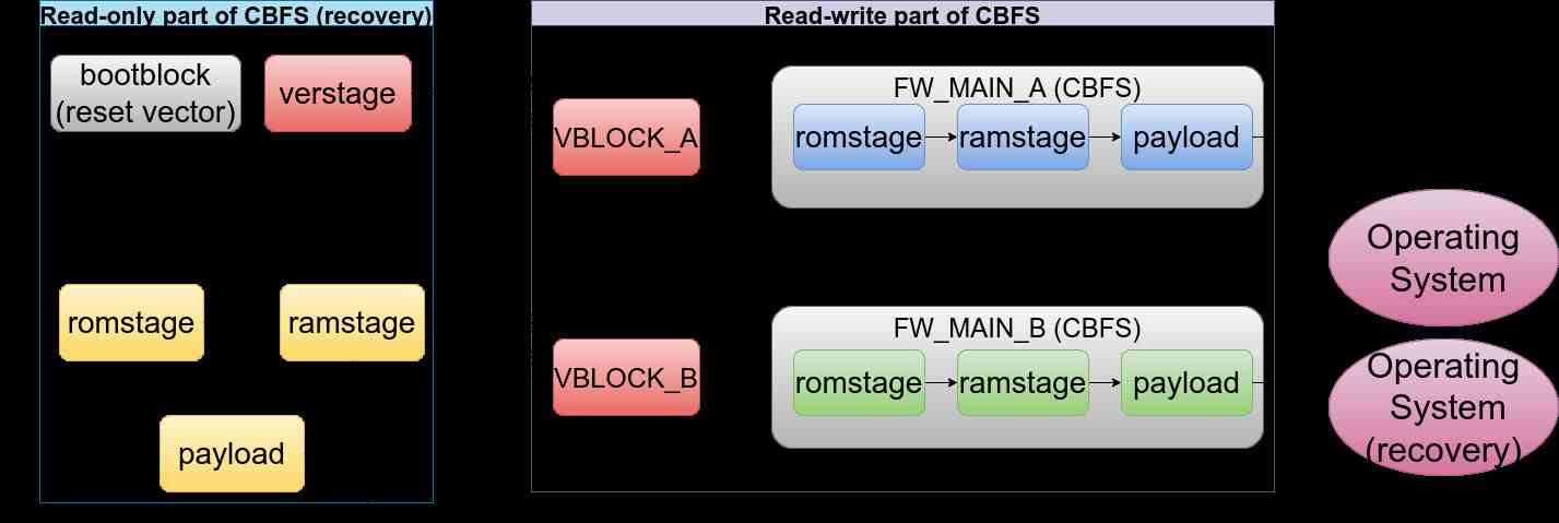
In case when vboot is enabled the protection range must be extended in order to cover other parts of the firmware. Vboot model assumes there is a read-only copy of the coreboot and payload called recovery partition. The recovery partition is supposed to be protected with a SPI write protection. The read-only region contains the bootblock, verstage (vboot stage used to verify other firmware components) and vboot keys and all other stages required to boot the platform in case of emergency. Typically the read-only partition occupies a space that matches the possible write protected regions of the flash chip. There are also read-write partitions (up to 2) that contain an updatable copies of the coreboot and payload. Unlike read-only partitions, read-write partitions are being verified using the signatures put into the read-write partitions. vboot checks the signature and decides whether read-write partition is safe to boot, otherwise it proceeds with execution of recovery firmware. The boot flow is shown on the diagram below:
In order to properly protect the firmware, one has to lock whole WP_RO region
define by flashmap in coreboot. To locate the region offset and size one has to
use cbfstool to retrieve layout:
cd /path/to/coreboot/build
./cbfstool coreboot.rom layout -w
This image contains the following sections that can be accessed with this tool:

'RW_MISC' (read-only, size 524288, offset 0)
'UNIFIED_MRC_CACHE' (read-only, size 131072, offset 0)
'RECOVERY_MRC_CACHE' (size 65536, offset 0)
'RW_MRC_CACHE' (size 65536, offset 65536)
'SMMSTORE' (preserve, size 262144, offset 131072)
'CONSOLE' (size 131072, offset 393216)
'RW_NVRAM' (size 16384, offset 524288)
'RW_SECTION_A' (read-only, size 5750784, offset 540672)
'VBLOCK_A' (size 8192, offset 540672)
'FW_MAIN_A' (CBFS, size 5742528, offset 548864)
'RW_FWID_A' (size 64, offset 6291392)
'WP_RO' (read-only, size 2097152, offset 6291456)
'RO_VPD' (preserve, size 16384, offset 6291456)
'RO_SECTION' (read-only, size 2080768, offset 6307840)
'FMAP' (read-only, size 2048, offset 6307840)
'RO_FRID' (size 64, offset 6309888)
'RO_FRID_PAD' (size 1984, offset 6309952)
'GBB' (size 16384, offset 6311936)
'COREBOOT' (CBFS, size 2060288, offset 6328320)

It is at least possible to perform the read action on every section listed above.
The above example shows the KGPE-D16 8MB target with vboot enabled. The WP_RO
section is at offset of 6291456 bytes from the beginning of the flash and has
size of 2097152 bytes. These numbers are in decimal, so one must convert them
to hex. Either use an online hex converter or use the command in bash like a
pro :)
printf "0x%x\n" 6291456
0x600000
printf "0x%x\n" 2097152
0x200000
So our WP range would be 2MB at 6MB offset
start=0x00600000 length=0x00200000 (upper 1/4). But before proceeding with
setting the WP range, one may want to sign the firmware with own vboot keys.
The Dasharo build come by default with Google vboot developer keys, so to take
advantage of vboot, one should sign the binary before flashing and setting the
WP range. Refer to
vboot signing.
Unfortunately the utilities support only 2 RW partitions for resiging.
Otherwise a whole image must be rebuilt. After custo mkeys have been used to
sign the ifmrware image and the image has been flashed proceed with enalbing
the protection:
./flashrom -p internal --wp-range=0x00600000,0x00200000
Then proceed with Setting SPI status register protection and Verifying SPI write protection.
At this point you should have your coreboot firmware with vboot well protected and ready to go. Place the jumper in order to prevent any changes to the configuration.