Recovery
Please read the overview page first!
Following documentation describes the process of recovering hardware from brick state with RTE and Dasharo open-source firmware. Following procedure is supported for following models
| Vendor | Model |
|---|---|
| Dell | OptiPlex 7010 SFF |
| Dell | OptiPlex 7010 DT |
| Dell | OptiPlex 9010 SFF |
Step 1: Prepare hardware
- To prepare hardware please follow hardware preparation procedure.
- Follow instruction in the video to remove heatsink:
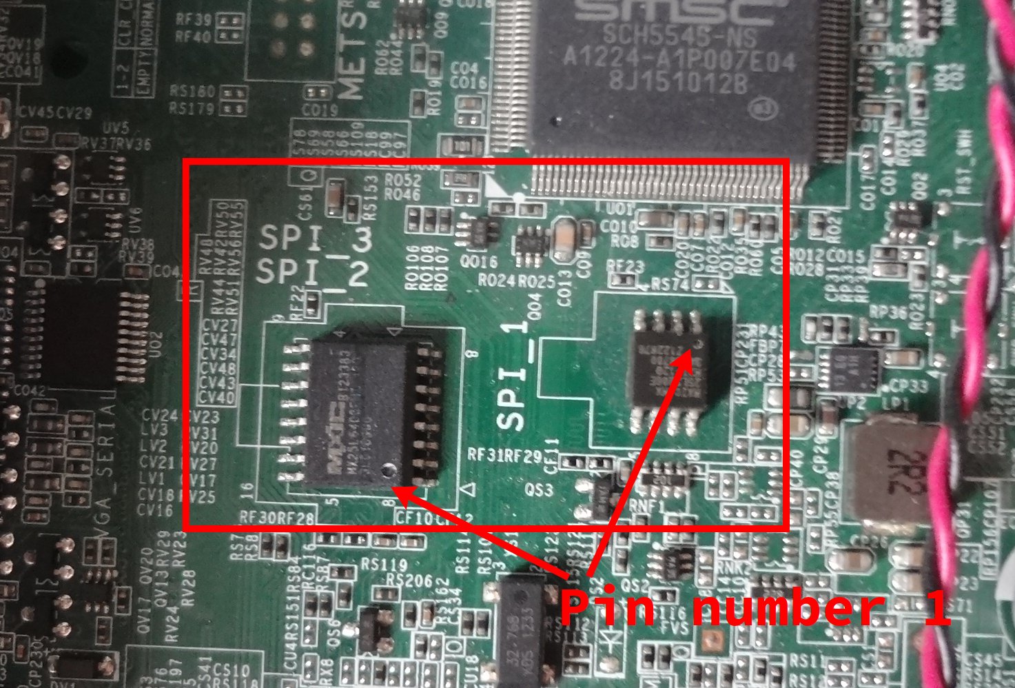
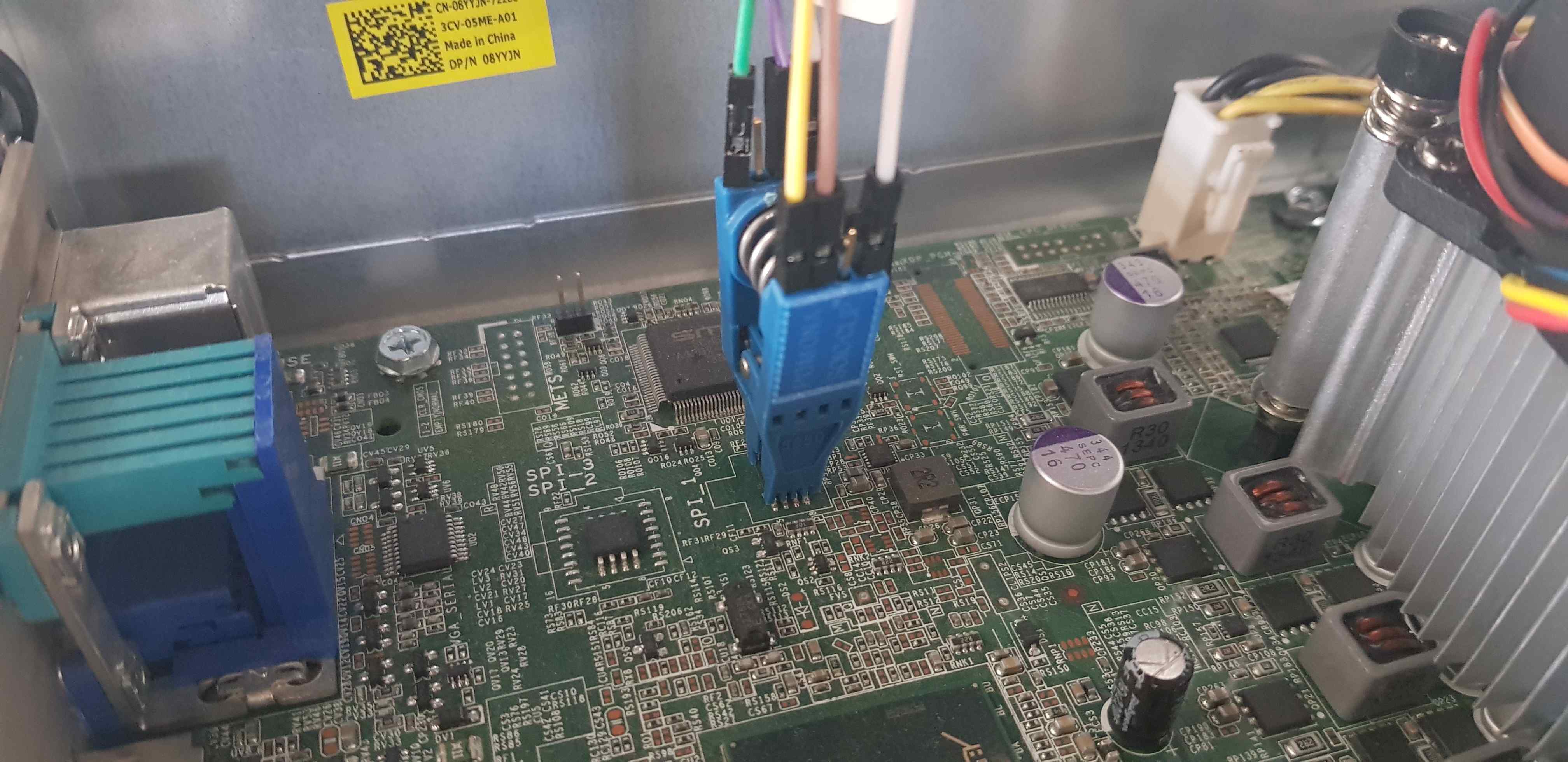
Step 2: Find SPI_1, SPI_2/SPI_3
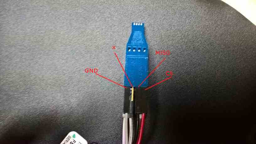
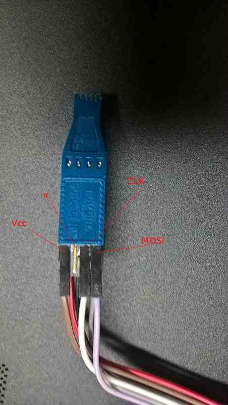
Step 3: Connect SOIC-8 Pomona clip between RTE and target
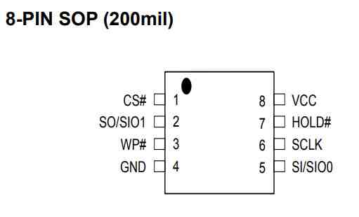
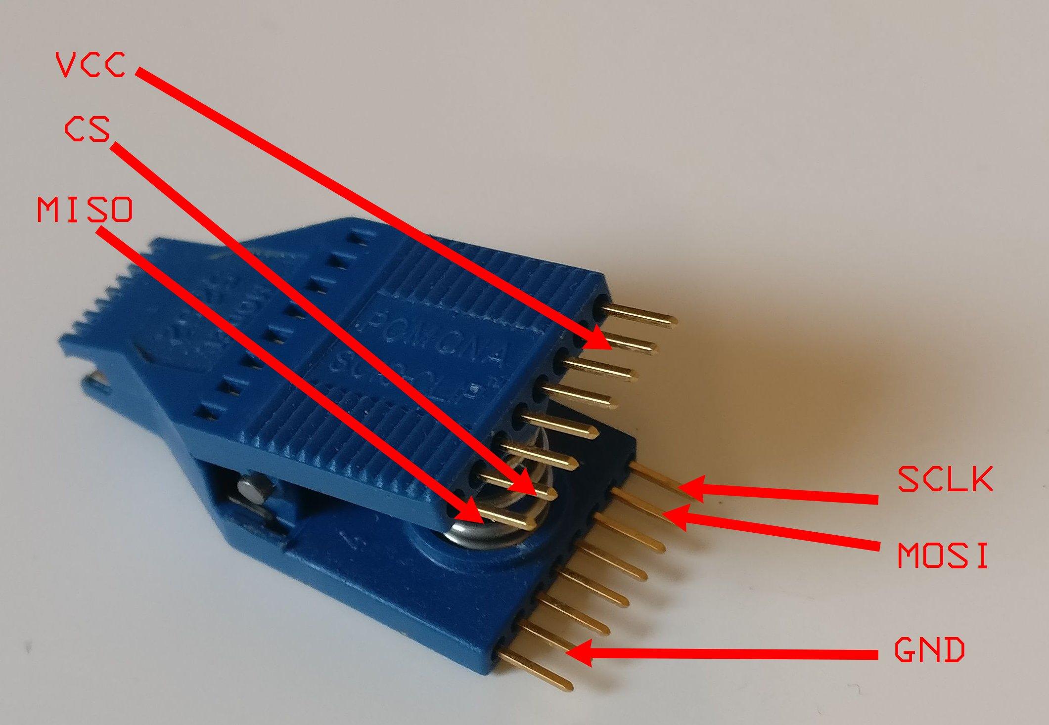
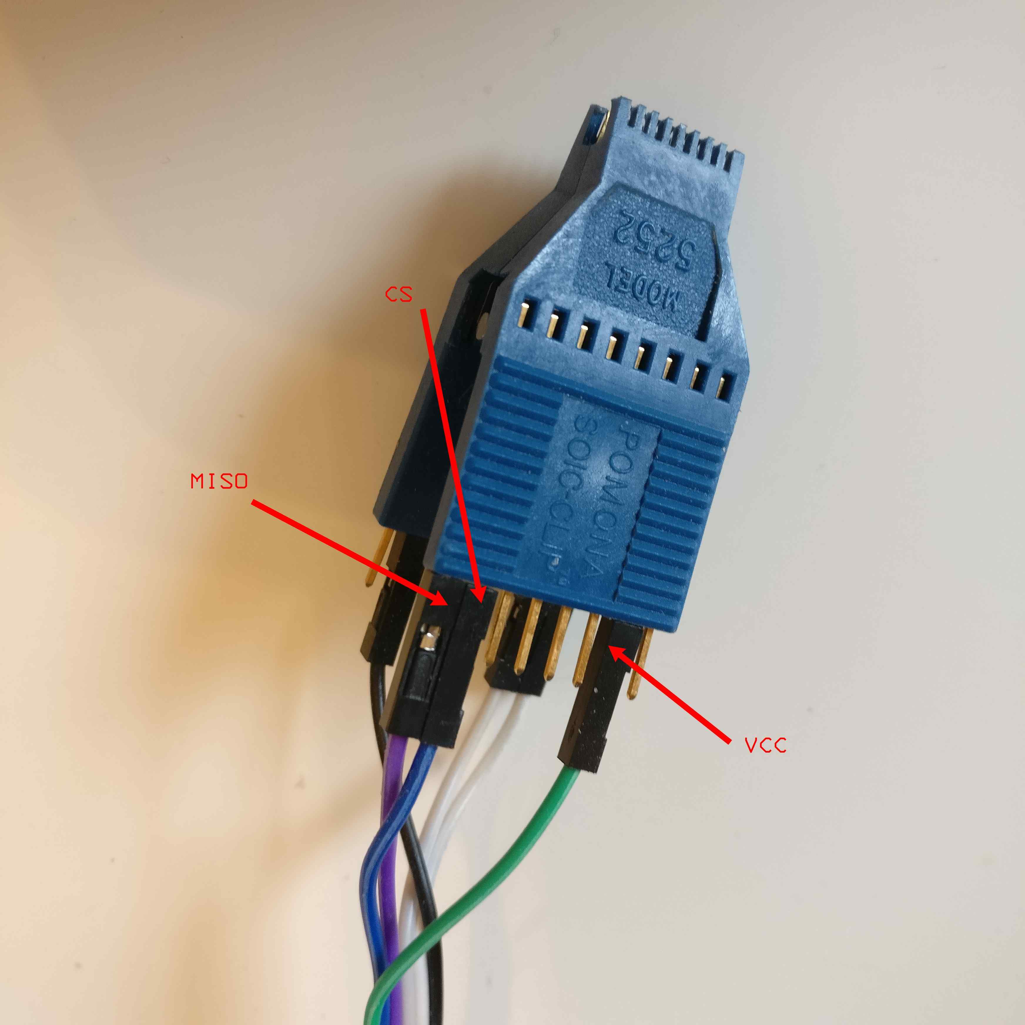
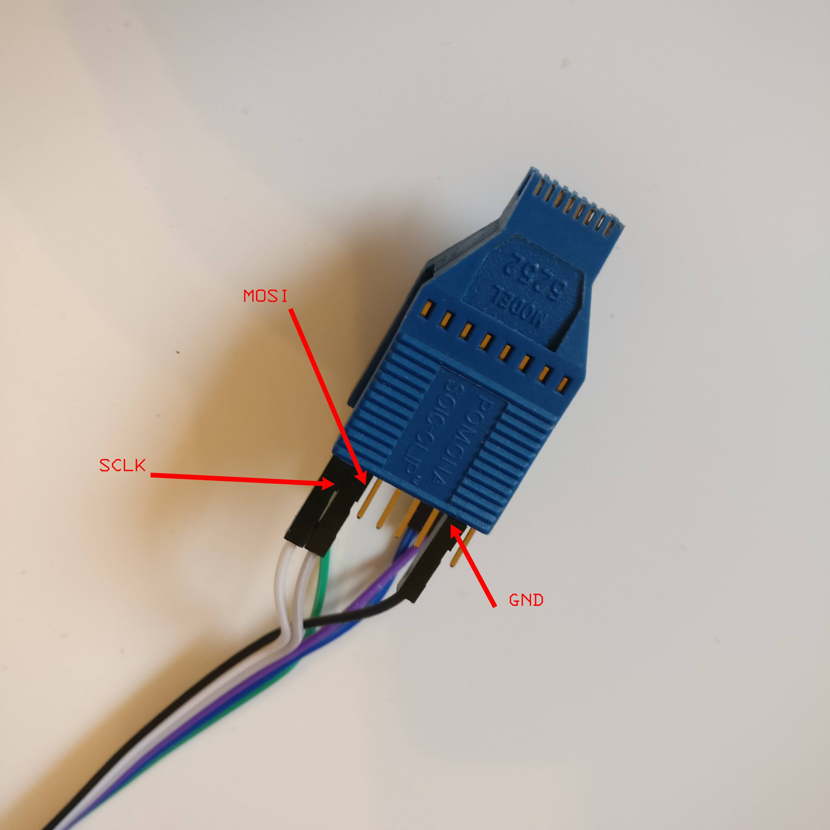
Connect SOIC-8 Pomona according to MX25L3206E datasheet.
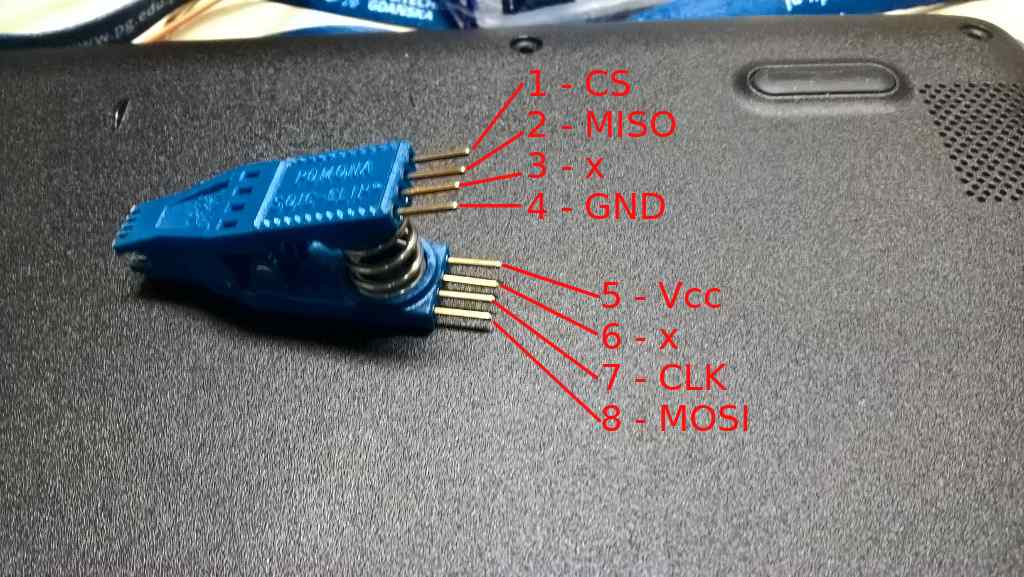
| RTE J7 | Pomona SOIC clip |
|---|---|
| CS | pin 1 (upside) |
| MISO | pin 2 (upside) |
| GND | pin 4 (upside) |
| VCC (3.3V) | pin 5 (downside) |
| SCLK | pin 7 (downside) |
| MOSI | pin 8 (downside) |
Numbers 1-4 have to be on one side and numbers 5-8 have to be on the other side of the clip.
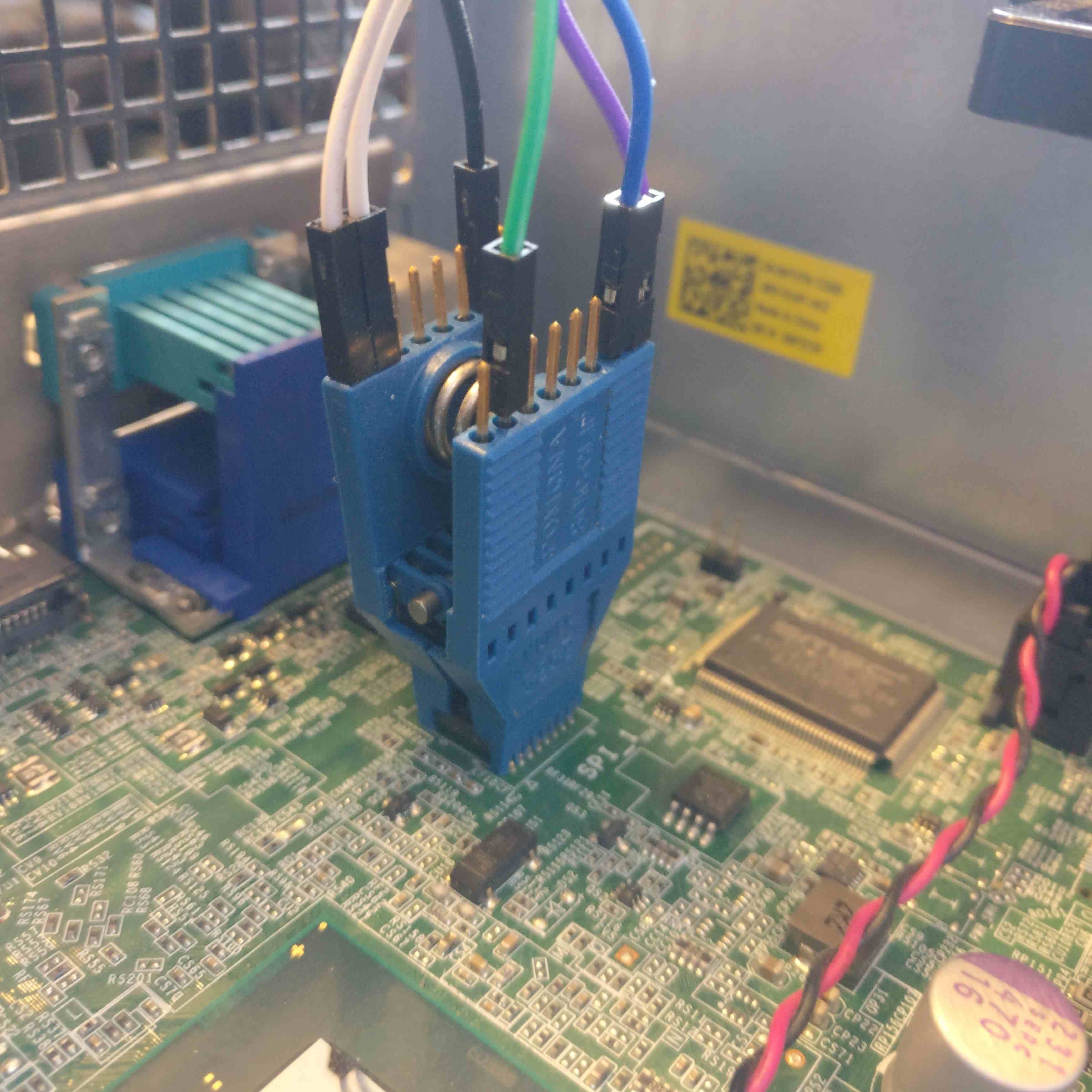
Clip on the SPI_1 chip. Match pin 1 (CS) of the Pomona clip with the first
pin of SPI_1 chip, marked with a small dot engraved on the chip.
Step 4: Connect RTE
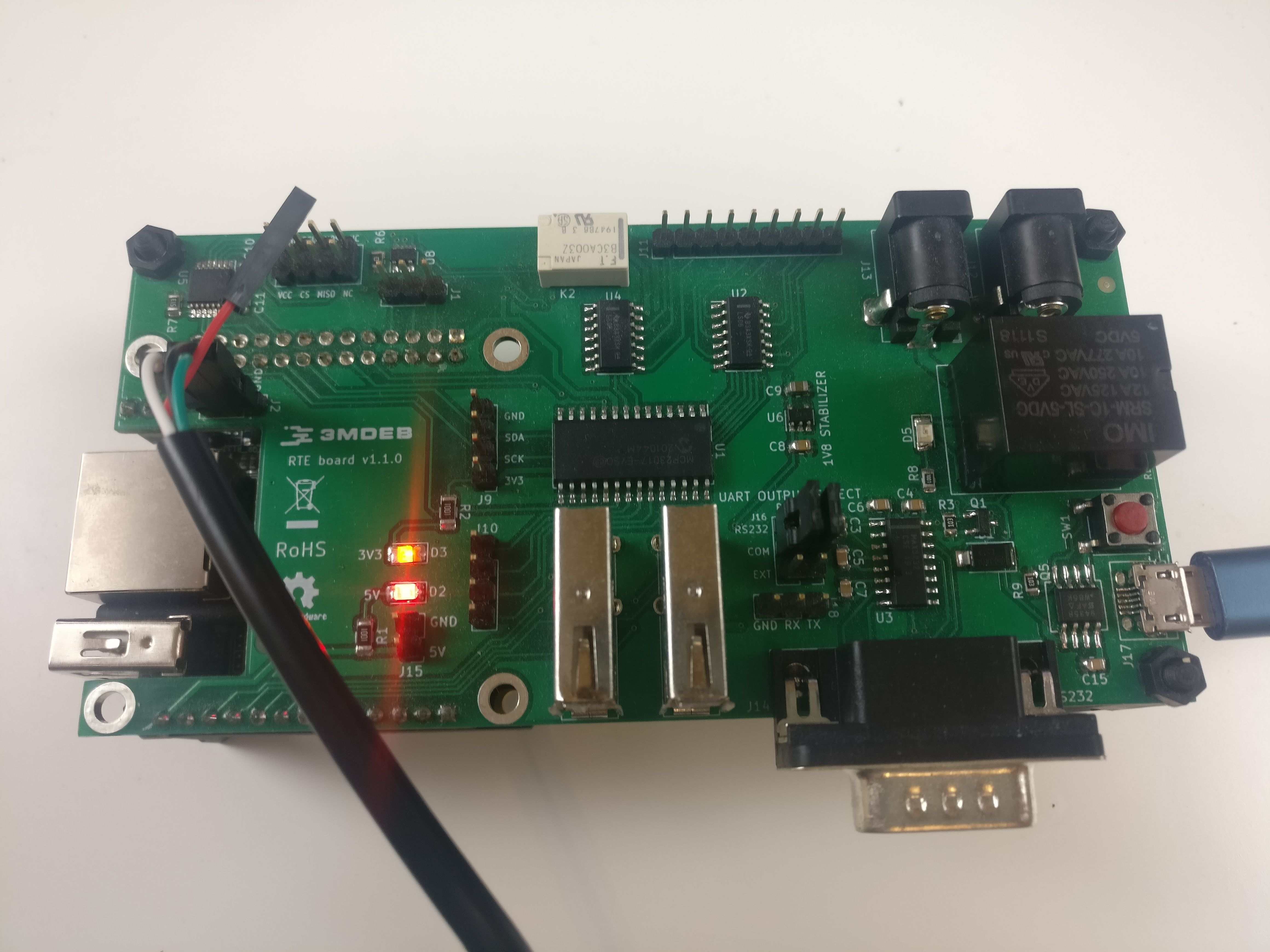
- Connect J2 Orange Pi Zero system debug output
- Power the board and confirm it boots
- Please note typical convention of USB-UART converter colors is as follows
- black - GND
- red - +5V
- green - TX
- white - RX
-
Connect terminal to RTE and read OS version:
sudo minicom -b 115200 -D /dev/ttyUSB0 -o -C /tmp/minicom.cap-b 115200sets baudrate-D /dev/ttyUSB0points to USB-UART converter device, it can be different if you already have some devices connected or you use different operating system-oskip initialization-C /tmp/minicom.capcapture serial terminal output, if you will have problems with exercises please post this file- Login using following credentials:
login: root
password: meta-rte
Step 5: Prepare recovery binary
Following procedure assume that you use recovery binary created during backup process. Backup has 12MB, so it have to be split
split -b4M bios_backup_YYYYMMDD.bin
Step 6: Flash 4MB (BIOS) part
echo 1 > /sys/class/gpio/gpio405/value
echo 1 > /sys/class/gpio/gpio406/value
echo 1 > /sys/class/gpio/gpio404/value
xac is third file resulting from the previous binary split, so it contains
Dasharo code and data which fits into 4MB and in case of Dell OptiPlex
9010/7010 should be flashed to 4MB SPI.
flashrom -w xac -p linux_spi:dev=/dev/spidev1.0,spispeed=16000 -c "MX25L3205D/MX25L3208D"
(Optional) Step 7: Flash 8MB (ME) part
If a more serious problem occurs, like broken ME, or if you would like to restore Dell firmware, it may be necessary to use your firmware backup and restore content of 8MB chip.
Step 7a: Connect SOIC-16 Pomona clip between RTE and target
Connect SOIC-16 Pomona according to MX25L6406E datasheet.
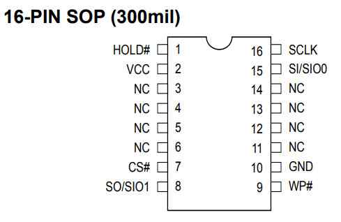
| RTE J7 | Pomona SOIC clip |
|---|---|
| VCC (3.3V) | pin 2 (upside) |
| CS | pin 7 (upside) |
| MISO | pin 8 (upside) |
| SCLK | pin 16 (downside) |
| MOSI | pin 15 (downside) |
| GND | pin 10 (downside) |
Numbers 1-8 have to be on one side and numbers 9-16 have to be on the other side of the clip.
Clip on the SPI_2/SPI_3 chip. Match pin 1 (HOLD#) of the Pomona clip with
the first pin of SPI_2/SPI_3 chip, marked with a small dot engraved on the
chip.
Step 7b: Flash 8MB (ME) part
echo 1 > /sys/class/gpio/gpio405/value
echo 1 > /sys/class/gpio/gpio406/value
echo 1 > /sys/class/gpio/gpio404/value
Dasharo recovery
Use following procedure if your 4M flash contain Dasharo open-source firmware.
cat > dell_optiplex.layout <<EOF
00000000:00000fff fd
00001000:00004fff gbe
00005000:005fffff me
00600000:007fffff unused
EOF
flashrom -w your_bios_backup.bin -p linux_spi:dev=/dev/spidev1.0,spispeed=16000 -c "MX25L6406E/MX25L6408E" -i fd -i me --layout dell_optiplex.layout
Vendor BIOS recovery
Use following procedure if your 4M flash contain vendor BIOS.
flashrom -w your_bios_backup_8M.bin -p linux_spi:dev=/dev/spidev1.0,spispeed=16000 -c "MX25L6406E/MX25L6408E"