Generic testing stand preparation
Introduction
This document aims to provide a comprehensive, generic guide to setting up a Remote Testing Environment for Dasharo platforms. As you follow along, please cross-examine with the motherboard's datasheets and our platform-specific recovery documentation, for example:
- Novacustom laptops recovery
- Dell OptiPlex recovery
- Asus KGPE-D16 recovery
- Raptor CS Talos II recovery
- Protectli platforms recovery
- MSI desktops recovery
- Supermicro X11 recovery
- PC engines platforms recovery
Note
This list is subject to change and extension. You can find all of our supported platforms and their respective sections on the Supported hardware page.
Detailed description of the process
If you are dealing with a new platform, you might want to first dump logs from it for future reference. We suggest using the dedicated functionality of DTS.
Compiling a list of peripherals
Before starting to set up the platform in the rack, make sure you plan it carefully. It is worth first determining what connections should be made on the stand, and then what equipment we need to be able to do it. When we put the device in a rack, we want to have remote access to it. Mainly used devices, depending on the functionalities needed:
Note
This documentation is based on RTE v1.1, which introduced significant changes over previous revisions. Using an earlier revision is not recommended, and may be problematic if not impossible with some platforms (e.g, if their flash chip requires 1.8V VCC!)
- Prepared RTE -
if we need low voltage control, switching on or off the platform, serial
connection and external flashing.
- SOIC-8 Pomona clip (if applicable, i.e. if there are no SPI flashing headers)
- 6x female-female wire cables
- Sonoff - if we need line voltage control.
- PiKVM - if it is not possible to read the device via serial or it is limited, it is possible to simulate the keyboard and read the image from HDMI.
Once we've collected everything, we can move on to setting up the equipment.
Remember
Two important rules while making connections and placing stand in the rack:
- Use ESD Strap: When assembling and connecting equipment in the lab, it is essential to use ESD straps. These straps help to prevent electrostatic discharge and protect sensitive electronic components from damage. Make sure you wear a strap every time you make a connection, and if someone is helping you, they have to also wear an ESD strap.
- Cut off the power supply: Before making any connections and ensure that the platform, RTE and any other components are disconnected from power. This precautionary measure reduces the risk of electrical accidents and protects both the equipment and you.
RTE setup
You need to examine the platform's motherboard and its manual to determine whether it has dedicated SPI headers, or will you have to use a Pomona clip to connect to the flash chip. If headers are present, they are preferred over Pomona connection for stability reasons.
For exact chip/header locations, see the platform-specific recovery guides in the corresponding Supported Hardware subsections, as mentioned in the introduction above.
This guide should cover for most of available platforms, however there are unique exceptions - for example MSI boards where we use the JTPM headers and a FlashBIOS button. Here, we will use Protectli VP46XX as a general example.
Before you proceed, make sure your RTE is prepared in accordance with this guide.
Connections
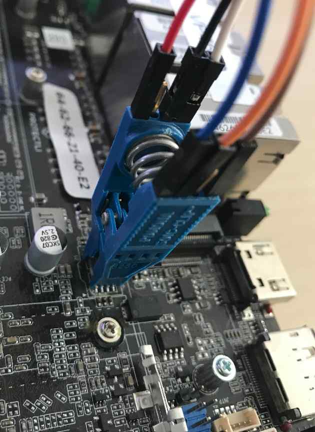
If your motherboard does not have SPI headers available, follow this guide for setting up a Pomona clip connection:
Pomona
-
Connect the wire cables to the Pomona clip.
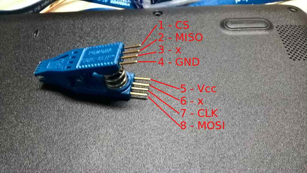
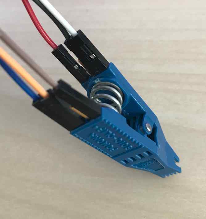
-
Connect the Pomona clip to the SPI header on RTE.
SPI header Pomona clip Vcc pin 5 (Vcc) GND pin 4 (GND) CS pin 1 (CS) SCLK pin 7 (CLK) MISO pin 2 (MISO) MOSI pin 8 (MOSI) 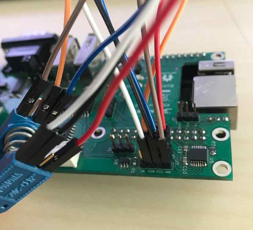
Note
In earlier RTE revisions, the VCC pin of the SPI header was not connected. In such case, you need to use a different 3.3V pin on the RTE instead.
-
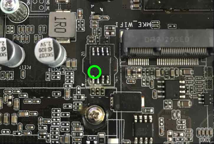
Open the platform cover and locate the SPI flash chip.
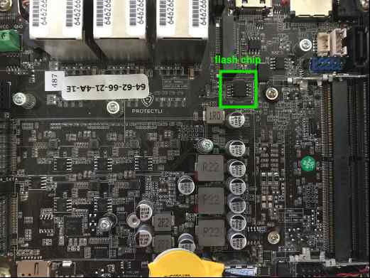
-
Match pin 1(CS) on the Pomona clip with the first pin of the flash chip, marked with a small dot engraved on the chip.
SPI headers
If your platform has dedicated SPI flash headers like the Protectli VP66XX, consider yourself lucky and simply connect corresponding pins with Dupont wires:
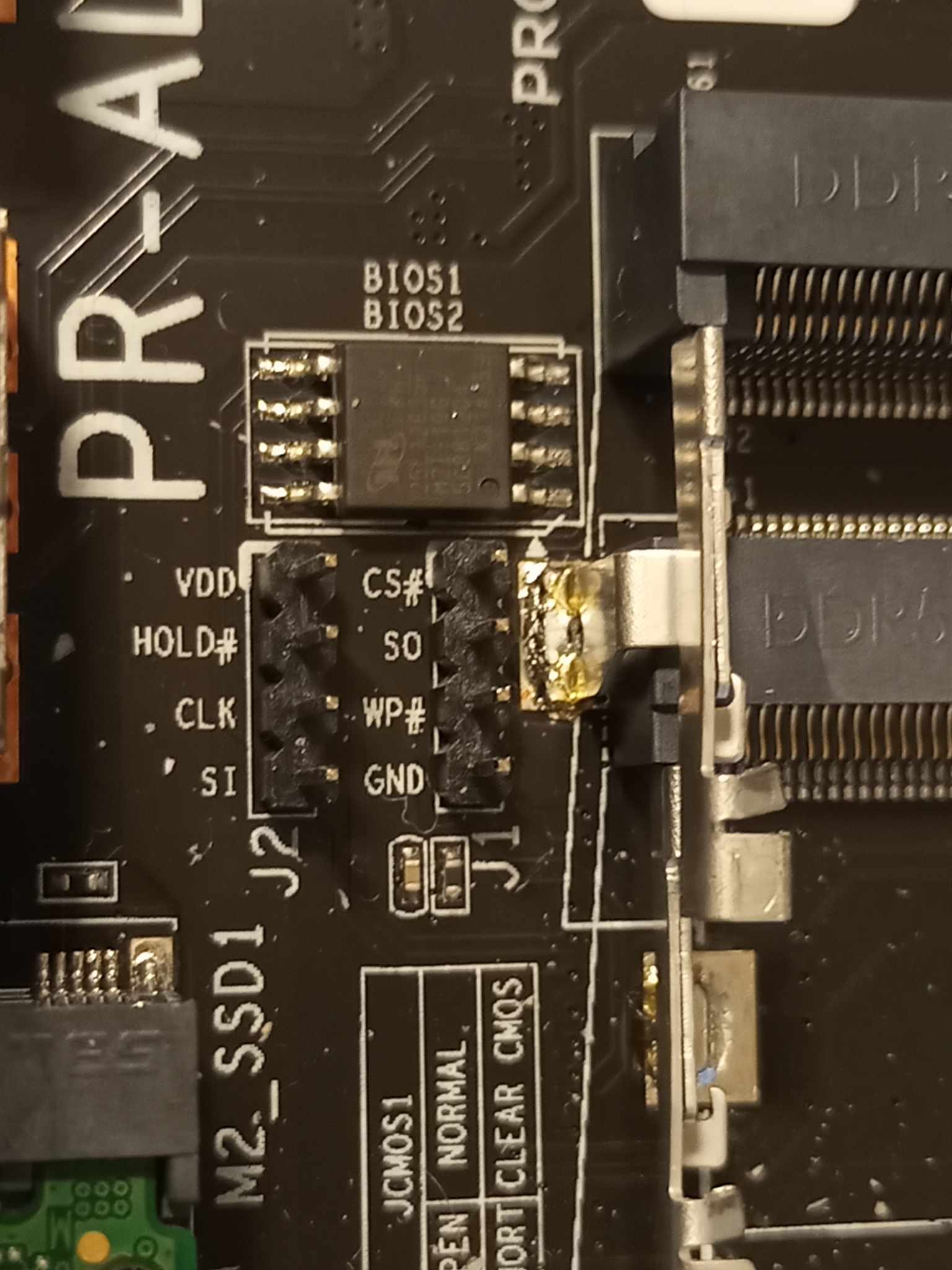
| SPI header | RTE |
|---|---|
| Vcc | Vcc |
| GND | GND |
| CS | CS |
| SCLK | CLK |
| MISO | MISO |
| MOSI | MOSI |
Note
In earlier RTE revisions, the VCC pin of the SPI header was not connected. In such case, you need to use a different 3.3V pin on the RTE instead.
Remaining pins
-
Locate CMOS headers and wire them to GPIO pins on the RTE according to the specification. You usually need to reset the CMOS after flashing for a successful firmware update.
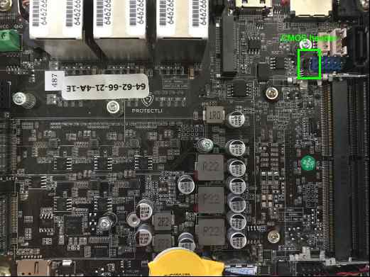
RTE DUT J11 pin 8 CLR_CMOS Any GND GND -
Locate the power and reset button pins. A motherboard will usually have a dedicated set of headers where the power and reset button wires are connected. Connect them to proper pins on the RTE according to specification.
RTE DUT J11 pin 6 PWR_BTN# J11 pin 5 RST# J15 pin 1 GND Reference schematic: RTE v1.1.0 PDF
Note
In RTE v1.0.0 or older, pins 8 and 9 are used for RST and PWR respectively. Reference schematic: RTE v1.0.0 PDF In extreme cases you might need to use clips to grab pins of soldered-in power and reset buttons.
-
Locate Power LED pin. A motherboard will usually have a dedicated set of headers where the power LED is connected, typically on the same header as power button and reset button wires are located. Connect the power LED to proper pin on the RTE according to specification.
RTE DUT J10 pin 1 PWR_LED On the schematics there might be no PWR_LED (or alike) signal. It is sufficient to connect
+V3.3Ssignal in that case (if available). Do not connect+V5Sas it may damage the RTE. Not all mainboards expose PWR_LED or+V3.3S, in such cases the connection must be omitted.
DC voltage supply control
If your device runs on DC voltage up to 24V, power management should be executed via RTE. Otherwise, skip to Sonoff setup.
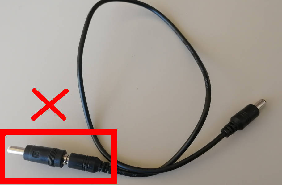
Connect 12-24V power supply to RTE J13 connector, then RTE J12 connector to DC connector. Do not use any DC jack adapters as these seem to introduce power losses and noises, making the power connection unstable.
Picture of the improper cable:
Picture of the proper cable:
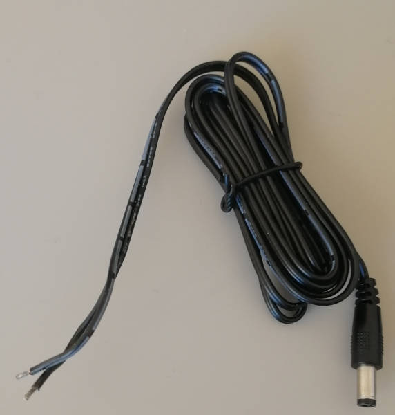
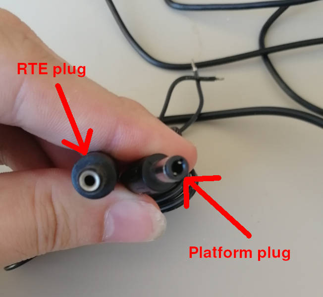
You have to solder the good cable with the half of bad cable to form a full cable. Cut the bad cable in half and strip the isolation. Take the red wire and solder it to the proper cables' white striped wire, this is the hot wire with positive voltage. Isolate the connection with a tape. Take the second black wire from the improper cable and solder it to the unstriped wire of the proper cable. Use tape to isolate and strengthen the whole connection. The cable is ready. Be sure to use plugs in the following way:
Sonoff setup
If you require line voltage control, follow our guide for Sonoff preparation.
PiKVM setup
If serial connection to the DUT is known to be problematic, follow our guide for PiKVM preparation.
Access to the DUT
Access to the DUT should be realized by connecting the serial port on the DUT to the serial port on RTE. The location of the serial port should be determined based on the platform's documentation. Documentation describing this process and including connections with various cables can be found here.
Follow the steps below to configure ser2net on RTE, which will allow you to
access the DUT via serial using the telnet console. In this example scenario, a
micro USB-USB converter is used to connect the DUT with RTE.
- Connect to RTE via ssh.
- Run the
dmesg -wcommand. - Disconnect and connect a micro USB-USB converter.
-
On the
dmesg -wcommand output look for the attached converter, in this case:[ 164.136255] usb 8-1: f81232 converter now attached to ttyUSB0 -
Then use vim to modify settings in
/etc/ser2net.yamlaccording to the port received from thedmesg -wcommand, in this case(ttyUSB0):connection: &con1 accepter: telnet, tcp, 13541 connector: serialdev, /dev/ttyUSB0, 115200n81, localconnection: &con2 accepter: telnet, tcp, 13542 connector: serialdev, /dev/debug_uart_converter, 115200n81, local -
Check access to the DUT using the
telnet <IP> <port>command.
In case you have multiple ttyUSB devices, you may want to assign persistent
names to them. In that case you need to define udev rules that will create the
device nodes. Create them in /etc/udev/rules.d/51-usb-converters.rules:
SUBSYSTEM=="tty" ACTION=="add", ATTRS{idVendor}==<vid>, ATTRS{idProduct}==<pid>, SYMLINK+="debug_uart_converter_<name>"
Replace <vid> and <pid> with the converter's vendor ID and product ID.
Then, specify the name in ser2net config:
connection: &con3
  accepter: telnet, tcp, <port>
  connector: serialdev, /dev/debug_uart_converter_<name>, 115200n81, local
You may need to change &con3 to another number, if 3 is already taken.
After making the changes you should reload udev rules and restart the ser2net
service:
udevadm control --reload-rules && udevadm trigger && systemctl restart ser2net
In case it is not possible to read the device via serial, set up PiKVM and properly connect to the platform. PiKVM setup documentation can be found here.
Platform external flashing
Platform external flashing is needed for two reasons:
- it enables quick changes to the firmware,
- it enables the process of unbricking the platform.
The flashing operation usually consists of several commands, involving crucial power management, so it is advisable to use our osfv-cli tool , providing support for most of Dasharo platforms.
Example use:
λ osfv_cli rte --rte_ip 192.168.10.244 flash probe
DUT model retrieved from snipeit: VP4630
Probing flash...
Executing command: flashrom -p linux_spi:dev=/dev/spidev1.0,spispeed=16000 -c MX25L12835F/MX25L12845E/MX25L12865E
flashrom v1.2 on Linux 5.4.69 (armv7l)
flashrom is free software, get the source code at https://flashrom.org

Using clock_gettime for delay loops (clk_id: 1, resolution: 1ns).
Found Macronix flash chip "MX25L12835F/MX25L12845E/MX25L12865E" (16384 kB, SPI) on linux_spi.

No operations were specified.
λ osfv_cli rte --rte_ip 192.168.10.244 flash read --rom vp4630-read.rom
DUT model retrieved from snipeit: VP4630
Reading from flash...
Executing command: flashrom -p linux_spi:dev=/dev/spidev1.0,spispeed=16000 -c MX25L12835F/MX25L12845E/MX25L12865E -r /tmp/read.rom
flashrom v1.2 on Linux 5.4.69 (armv7l)
flashrom is free software, get the source code at https://flashrom.org

Using clock_gettime for delay loops (clk_id: 1, resolution: 1ns).

Found Macronix flash chip "MX25L12835F/MX25L12845E/MX25L12865E" (16384 kB, SPI) on linux_spi.

Reading flash...
done.

Read flash content saved to vp4630-read.rom
Flashing with flashrom takes about 1 minute.
Note that the first boot of the platform after proceeding with above procedure can take much longer than usual.
Stand Setup
Before placing the stand in the lab, it is recommended to set it up first at
your desk to verify its functionality. After compiling the stand, the
connections that we have made should be checked. The necessary thing to do the
check is the IP address of RTE which we can get by connecting to RTE via serial
using minicom and using the ip a command.
After this, we have an IP to connect via ssh. This process should suit every position:
- Connect to RTE via ssh.
- Check access to the DUT using the
telnet <IP> <port>command from RTE or log in to PiKVM by entering its IP address in your browser. -
Check that the commands responsible for the power control are working properly:
osfv_cli rte --rte_ip 192.168.10.244 rel tglosfv_cli rte --rte_ip 192.168.10.244 pwr onosfv_cli rte --rte_ip 192.168.10.244 pwr offosfv_cli rte --rte_ip 192.168.10.244 pwr reset -
Check the flashing connections using a prepared flashing script.
- Check for additional connections.
Placement in the Lab
After testing the functionalities of the stand, follow these guidelines to place it in the lab:
- Select an appropriate location in the rack cabinet for the stand. Consider safety, accessibility, and proper fastening of the station elements.
- Ensure that the cables are routed through trays and securely tied to prevent them from sticking out or becoming tangled.
- Label the cables and elements of the stand with their IP addresses for easy identification.
- Once the stand is in place, recheck the connections, ensuring that all cables are properly connected and secured.
- Complete the setup by checking remote access to the stand via SSH and ensure that all functions are working correctly.
Additional steps
You might want to assign a static IP address for the RTE to avoid connection problems in the future. It can also prove useful to make a documentation of your entire test setup and enlist it in an IT asset management system, such as SnipeIT - providing such information in an issue report might turn out to be crucial.