muxPi board validation
In case of any troubles, first it is recommended to read comprehend Theory of Operations for muxPi devices.
Necessary components preparation
- NanoPi
- muxPi
- ETH, microUSB<->USB cables, power supply (5V/2A Dc 5.5/2.1mm jack)
- 2 SDcards (minimum 8GB each)
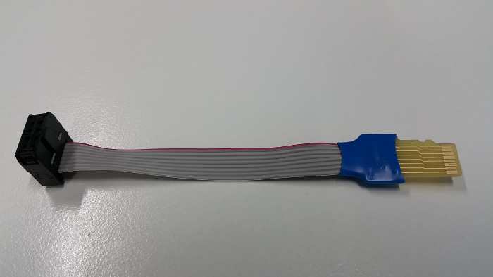
- IDC-uSD adapter (DUT<->SD card)
- SD card adapter (USB<->SD card)
- Device bootable from SD card (e.g. RPI)
NanoPi setup
- Prepare microSD card (minimum 8GB) for NanoPi NEO operating system.
- Download and extract image - link.
- Flash image into microSD card (Etcher tool could be helpful)
muxPi setup
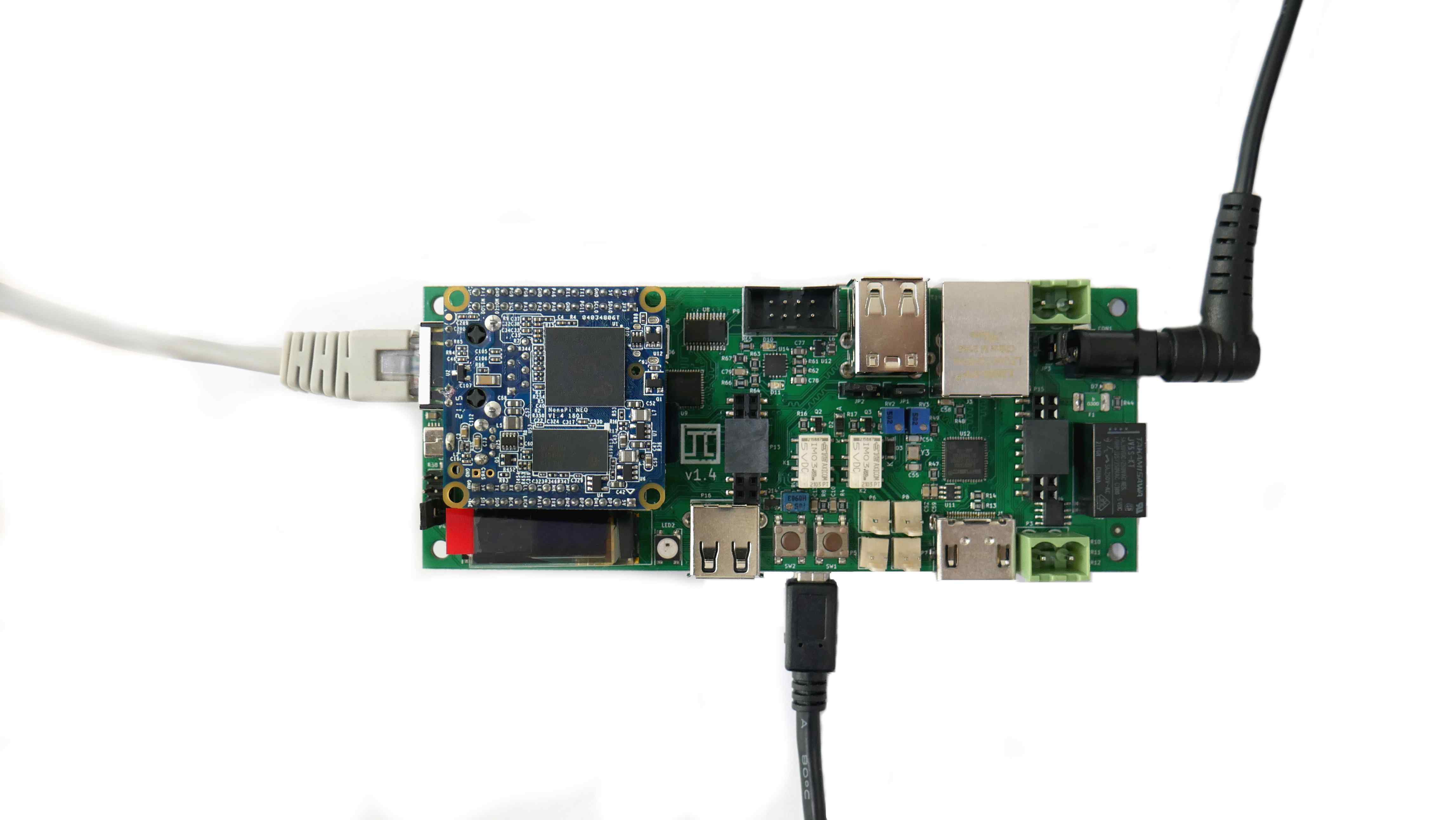
- Attach NanoPi to muxPi connectors.
- Plug ETH cable to RJ45 NanoPi port.
- Plug microUSB<->USB cable to muxPi and your machine.
- Plug in power supply.
-
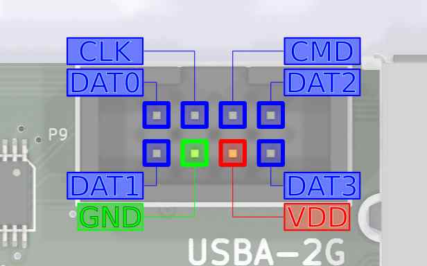
Make sure that jumpers are correctly set according to image:
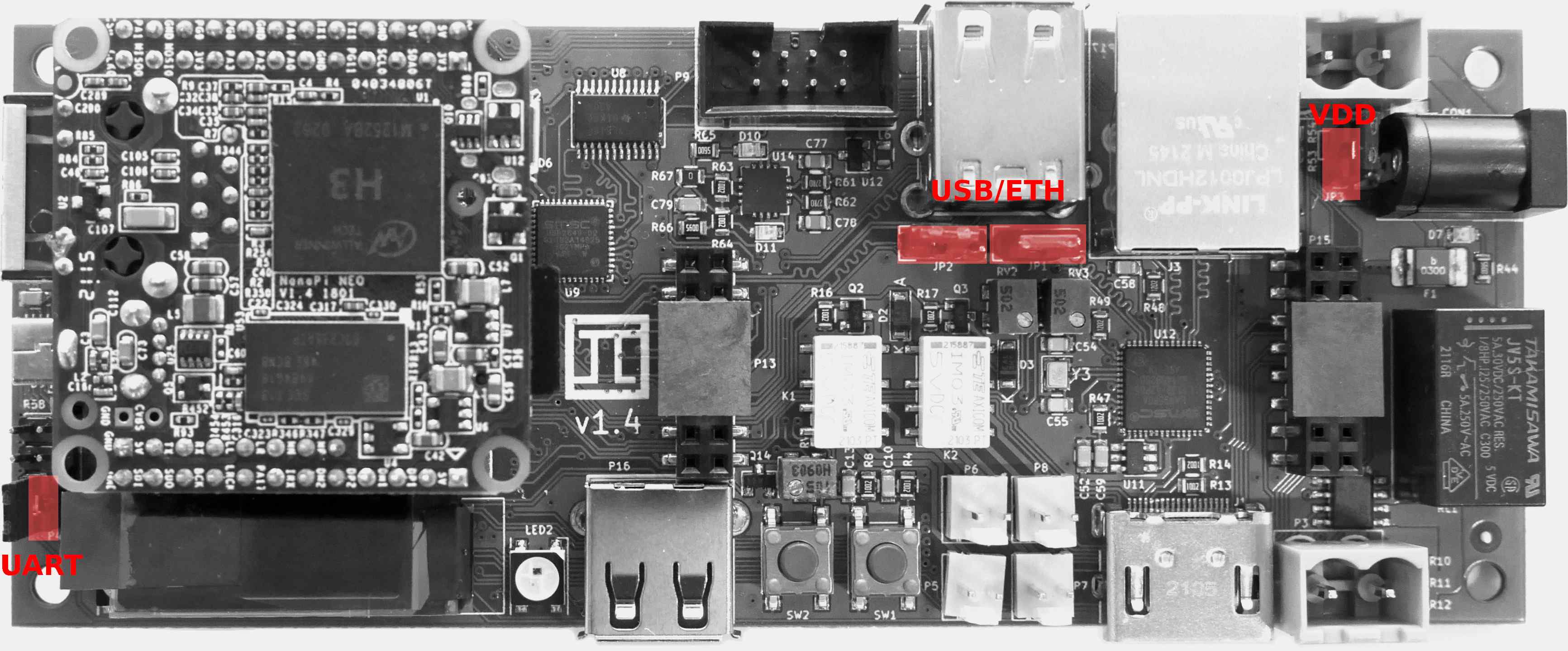
-
Connect to NanoPi using terminal:
sudo minicom -D /dev/ttyUSB0 -o -b 115200` -
Save ip address:
ifconfig -
Connect to NanoPi via ssh (with password:
fa):bash ssh root@192.168.4.XXX -
Or via serial connection.
NOTE: Connecting with MuxPi through serial will automatically login as non root user
piwith passwordpi.
Validation steps
1. Install WiringNP
 git clone https://github.com/friendlyarm/WiringNP
 cd WiringNP/
 chmod 755 build
 ./build
- verify installation:
gpio readall
- If your installation is successful the following messages will show up:
 +-----+-----+----------+------+---+-NanoPi-NEO--+------+----------+-----+-----+
 | BCM | wPi |   Name   | Mode | V | Physical | V | Mode | Name     | wPi | BCM |
 +-----+-----+----------+------+---+----++----+---+------+----------+-----+-----+
 |     |     |     3.3V |      |   |  1 || 2  |   |      | 5V       |     |     |
 |  12 |   8 |  GPIOA12 | ALT5 | 0 |  3 || 4  |   |      | 5V       |     |     |
 |  11 |   9 |  GPIOA11 | ALT5 | 0 |  5 || 6  |   |      | 0v       |     |     |
 | 203 |   7 |  GPIOG11 |  OFF | 0 |  7 || 8  | 0 | ALT5 | GPIOG6   | 15  | 198 |
 |     |     |       0v |      |   |  9 || 10 | 0 | ALT5 | GPIOG7   | 16  | 199 |
 |   0 |   0 |   GPIOA0 | ALT5 | 0 | 11 || 12 | 0 |  OUT | GPIOA6   | 1   | 6   |
 |   2 |   2 |   GPIOA2 |  OFF | 0 | 13 || 14 |   |      | 0v       |     |     |
 |   3 |   3 |   GPIOA3 |  OFF | 0 | 15 || 16 | 0 |  OFF | GPIOG8   | 4   | 200 |
 |     |     |     3.3v |      |   | 17 || 18 | 0 |  OFF | GPIOG9   | 5   | 201 |
 |  64 |  12 |   GPIOC0 | ALT4 | 0 | 19 || 20 |   |      | 0v       |     |     |
 |  65 |  13 |   GPIOC1 | ALT4 | 0 | 21 || 22 | 0 | ALT5 | GPIOA1   | 6   | 1   |
 |  66 |  14 |   GPIOC2 | ALT4 | 0 | 23 || 24 | 1 |  OUT | GPIOC3   | 10  | 67  |
 +-----+-----+----------+------+---+----++----+---+------+----------+-----+-----+
 | BCM | wPi |   Name   | Mode | V | Physical | V | Mode | Name     | wPi | BCM |
 +-----+-----+----------+------+---+-NanoPi-NEO--+------+----------+-----+-----+

 +-----+----NanoPi-NEO USB/Audio-+----+
 | BCM | wPi |   Name   | Mode | V | Ph |
 +-----+-----+----------+------+---+----+
 |     |     |       5V |      |   | 25 |
 |     |     |  USB-DP1 |      |   | 26 |
 |     |     |  USB-DM1 |      |   | 27 |
 |     |     |  USB-DP2 |      |   | 28 |
 |     |     |  USB-DM2 |      |   | 29 |
 |     |     |    IR-RX |      |   | 30 |
 |  17 |  19 |  GPIOA17 |  OFF | 0 | 31 |
 |     |     |  PCM/I2C |      |   | 32 |
 |     |     |  PCM/I2C |      |   | 33 |
 |     |     |  PCM/I2C |      |   | 34 |
 |     |     |  PCM/I2C |      |   | 35 |
 |     |     |       0V |      |   | 36 |
 +-----+-----+----------+------+---+----+

 +-----+----NanoPi-NEO Debug UART-+----+
 | BCM | wPi |   Name   | Mode | V | Ph |
 +-----+-----+----------+------+---+----+
 |   4 |  17 |   GPIOA4 | ALT5 | 0 | 37 |
 |   5 |  18 |   GPIOA5 | ALT5 | 0 | 38 |
 +-----+-----+----------+------+---+----+
2. Cortex-M0 flashing
The second controllable unit on the muxPi board is embedded microcontroller
STM32 F030C6T6 from Cortex-M0 family. It is required to flash special binary
prepared by Tizen group (the code is not open yet, but this process is in
progress). To flash muxPi's microcontroller, follow steps below:
- Make sure that VDD jumper is left open.
- Download binary file - link.
- Copy binary to nanoPi:
scp <path-to-file> root@192.168.4.XXX:/root/ - Update package lists (nanoPi):
apt-get update - Install stm32flash utility (nanoPi):
sudo apt-get install stm32flash - Export GPIO:
gpio mode 3 outandgpio mode 7 out - Set Cortex-M0 to "Flashing mode":
gpio write 7 1 - Power up microcontroller:
gpio write 3 1 - Flash firmware:
stm32flash -w /root/firmware-05.bin -v -g 0x0 /dev/ttyS2 - Power off microcontroller:
gpio write 3 0 - Set Cortex-M0 to "Execution mode":
gpio write 7 0 - Power on microcontroller:
gpio write 3 1
From now on, muxPi's LCD should light on and display:
    *  MuxPi  *
    HW: 1.0 SW: 0.5
3. SD Adapter
-
Connect IDC-uSD adapter to the muxPI board:
-
Insert the microSD card to microSD card slot accessible on the bottom side of muxPi board.
-
To enable microSD card reader, connect to Cortex from MuxPi via minicom:
minicom -D /dev/ttyS2and enter in minicom following commands:
tsand then
dutNOTE: Each command should return
OK -
Connect IDC-uSD adapter to a SD card adapter plugged into your machine
NOTE: You need to force IDC-uSD adapter to insert into SD card adapter
-
(On your machine) Check if device is connected:
dmesg -wshould help. You should also be able to read and write data to uSD card from file manager. - Flash image into microSD card (for RPI or other device bootable form SD card).
- Disconnect uSD adapter form a SD card adapter and connect to the device (e.g. RPI).
- Connect device to the power supply, now device should boot via IDC-uSD adapter.
4. Screening
- It is recommended to use screen program for communication:
- Install screen:
sudo apt-get install screen - Open connection (from muxPi):
screen /dev/ttyS2 115200,cs8,ixon,ixoff - Write
helpand press Enter.
Help output:
help --- This help
version --- Display version of the firmware
echo --- Get (no arguments) or set ('on' or 'off') echo on serial "console": echo [on|off]. The default value is on.
power --- Get (no arguments) or set ('on' or 'off') or switch off and on ('tick') power supply for DUT: power [on|off|tick]
hdmi --- Get (no arguments) or set ('on' or 'off') HDMI HOTPLUG pin: hdmi [on|off]
dyper --- Get (no second argument) or set ('on' or 'off') DyPer state: dyper 1|2 [on|off]
 mux --- Connect microSD card to external connector (DUT) or card reader (ts): mux [dut|ts]
 dut --- Connect microSD card and power to DUT: dut
  ts --- Connect microSD card and power to TS: ts
 led --- Get (no second or third argument) or set ('R G B') color of led (1 | 2), ex: led 1 255 0 255
 clr --- Clear oled display
text --- Print text on the OLED display: text x y color content
draw --- Draw an object on the OLED display: draw object x1 y1 [x2 y2], objects are:
         - point x y color - draws one point at given coordinates
         - line x1 y1 x2 y2 color - draws line between given coordinates
         - rectangle left top width height color - draws line between given coordinates
         - circle x y radius color - draws line between given coordinates
color must be 'on', 'off' or 'inv'
 adc --- Print current adc value of all (if no arguments are given) or one specified channel, ex: adc 1
voltage --- Print current voltage [mV] of all (if no arguments are given) or one specified channel, ex: voltage 1
current --- Print current current [mA] being consumed by DUT
lthor --- Get (no second argument) or set state of lthor control signals:
         - lthor switch [usb|uart] - redirect DUT's USB wires to NanoPi's 'usb' or 'uart'
         - lthor id [usb|uart] - switch DUT's USB to 'usb' or 'uart' mode
         - lthor vbus [on|off] - switch DUT's VBUS 'on' or 'off'
         - lthor combo [usb|uart] - make DUT and MuxPi USB work in 'usb' or 'uart' mode - no get function

 key --- Get current state of given key or both if no key number is given: key [1|2]
uart --- Get current value of UART voltage or set if new value is given [in millivolts]
NOTE:
helpmight not display anything. Then try to use minicom.
Minicom quick guide:
- Install minicom:
sudo apt-get install minicom - Connect via minicom:
sudo minicom -D /dev/ttyS2 -o -b 115200 -
Type:
helpNOTE: If output is the same as above then basic validation for muxPi is done.
Images source: Wiki Tizen