Dasharo compatible with MinnowBoard Turbot - lab assembly guide
Intro
This document gathers various notes and documentation useful for development of Dasharo compatible with the MinnowBoard Turbot platform.
Hardware connection
Requirements
-
USB-UART converter
-
DC Jack - DC Jack wire
Serial
MinnowBoard exposes a pin header with debug UART on J4.
- Attach the pins on MinnowBoard to the USB-UART converter.
| USB-UART converter | Minnowboard Uart header (J4) |
|---|---|
| GND | 1 (GND) |
| TX | 4 (RX) |
| RX | 5 (TX) |
SPI
| RTE header J7 pin | Minnowboard header J1 pin |
|---|---|
| 1 (NC) | 3.3V connect from RTE J9 pin 1 |
| 2 (GND) | 2 (GND) |
| 3 (CS) | 3 (SPICS#) via 1.2 kOhm resistor |
| 4 (SCLK) | 4 (SPICLK) |
| 5 (MISO) | 5 (SPIDI) |
| 6 (MOSI) | 6 (SPIDO) |
| 7 (NC) | Not connected |
| 8 (NC) | Not connected |
Power supply
- Connect 5V power supply to RTE
J12connector - Connect RTE
J13connector to MinnowBoardJ9connector with a DC Jack - DC Jack wire
You can control the power supply using the osfv_cli tool:
osfv_cli rte --rte_ip <rte-ip> --model minnowmax rel tgl
- Power switch can also be controlled from the RTE. Connect the power control pins according to the following table:
| RTE | MinnowBoard |
|---|---|
| J11 Pin 9 | J5 Pin 1 |
| J15 GND | J5 Pin 2 |
The power state can be controlled with the osfv_cli script:
osfv_cli rte --rte_ip <rte-ip> --model minnowmax pwr on
osfv_cli rte --rte_ip <rte-ip> --model minnowmax pwr off
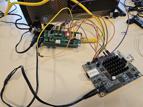
- Example setup:
Flashing firmware
You can flash firmware with the osfv_cli tool. Before trying to flash make
sure that SPI is connected properly.
osfv_cli rte --rte_ip <rte_ip> --model minnowmax flash write --rom <path_to_binary>