Laboratory stand dedicated to MSI PRO Z690-A assembly guide
Introduction
This document describes platform-specific details for assembling an MSI PRO Z690-A testing stand. Use this document as reference while going through Generic Testing Stand Setup
Prerequisites
The below table contains information about all elements which are needed to create the testing stand.
- MSI PRO Z690-A platform
- RTE v1.1.0
- Sonoff S20 type E
- 4x standard female-female connection wire 2.54 mm raster
- 7x standard female-female connection wire 2.54/2.00 mm raster
- USB-UART converter with 4-wire cable
- 4-pin header 2.54 mm raster
MSI PRO Z690-A
MSI PRO Z690-A platform should be prepared in accordance with the Motherboard assembly documentation.
Connections
The following sections describe how to enable all of the following features:
- serial connection to the platform,
- controlling power supply,
- enabling basic power actions with the platform (power off/power on/reset),
- external flashing with the RTE,
- device power status readout.
Serial connection
-
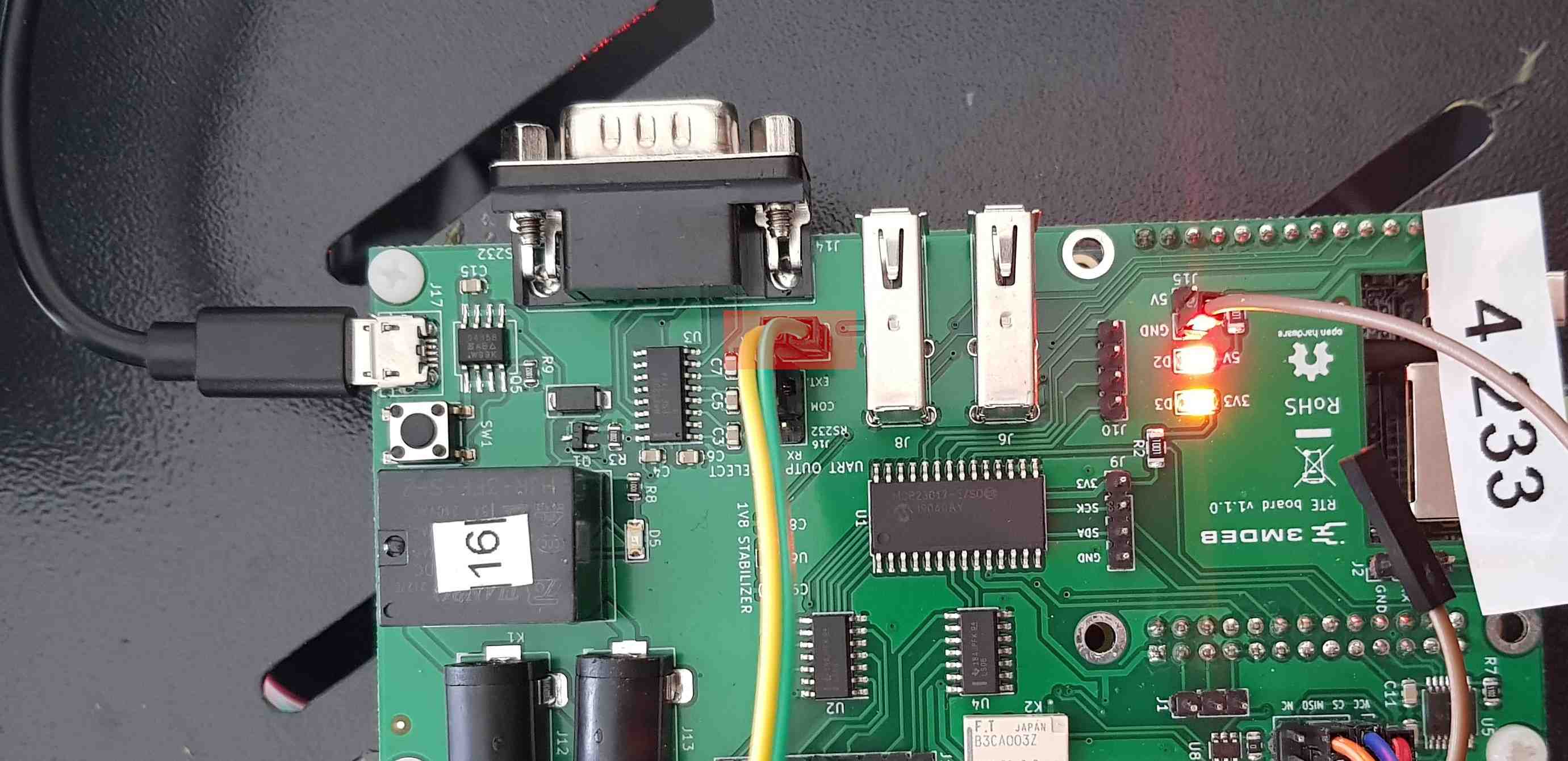
Attach the jumpers in the RTE J16 header to enable header J18:
Jumper position (TX) Jumper position (RX) EXT + COM EXT + COM -
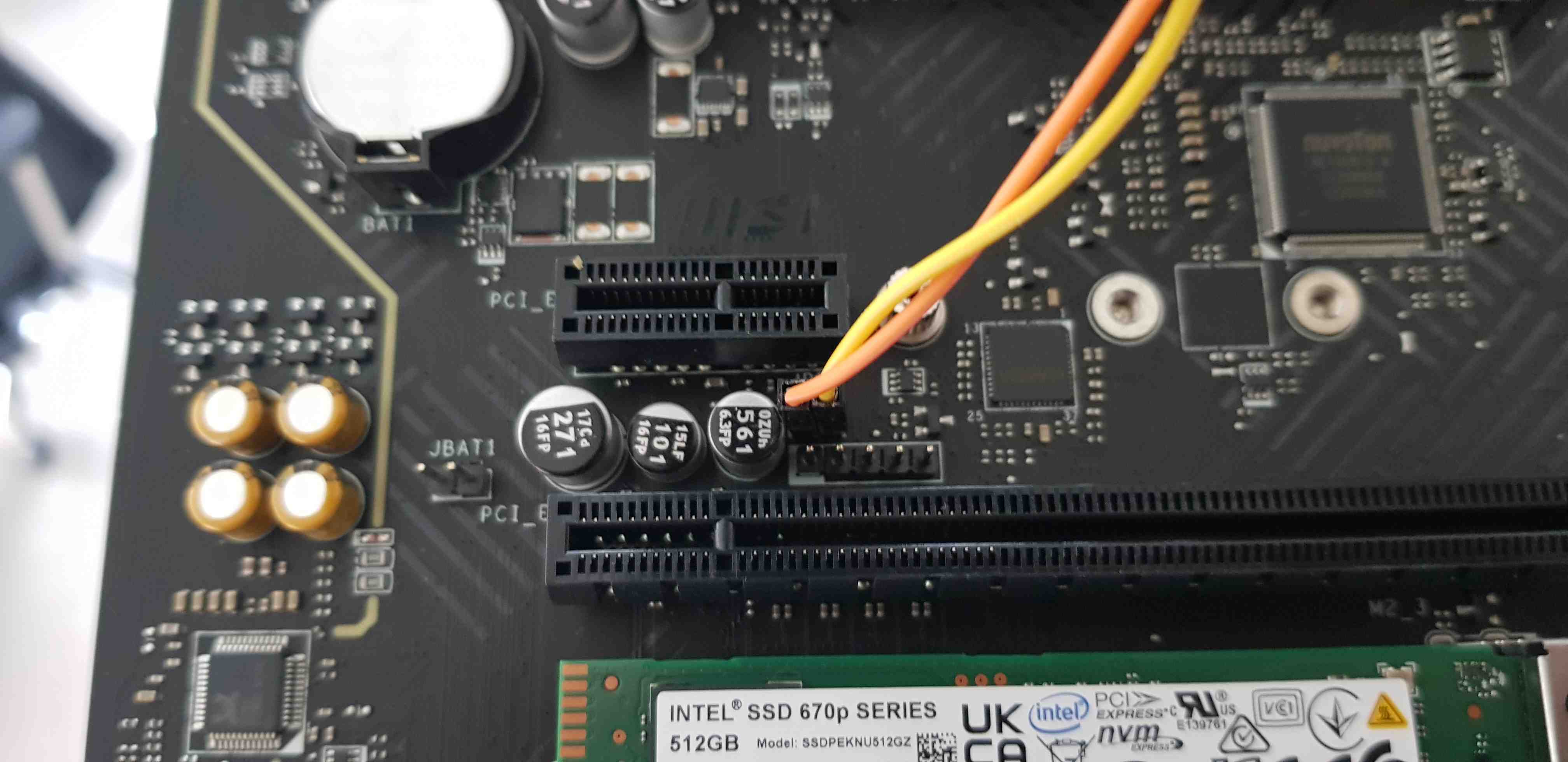
Connect the RTE J18 header to the platform JBD1 header as described in the table:
RTE MSI PRO Z690-A J18 pin 1 (GND) JBD1 pin 1 (pin closer to JBAT1) J18 pin 2 (RX) JBD1 pin 2 (pin further from JBAT1) Note: Pins on JBD1 are not described in the documentation. They have been discovered experimentally. Pay attention to the connections.
Power supply controlling
Connect SeaSonic FOCUS Plus Platinum to Sonoff.
Basic power operations enabling
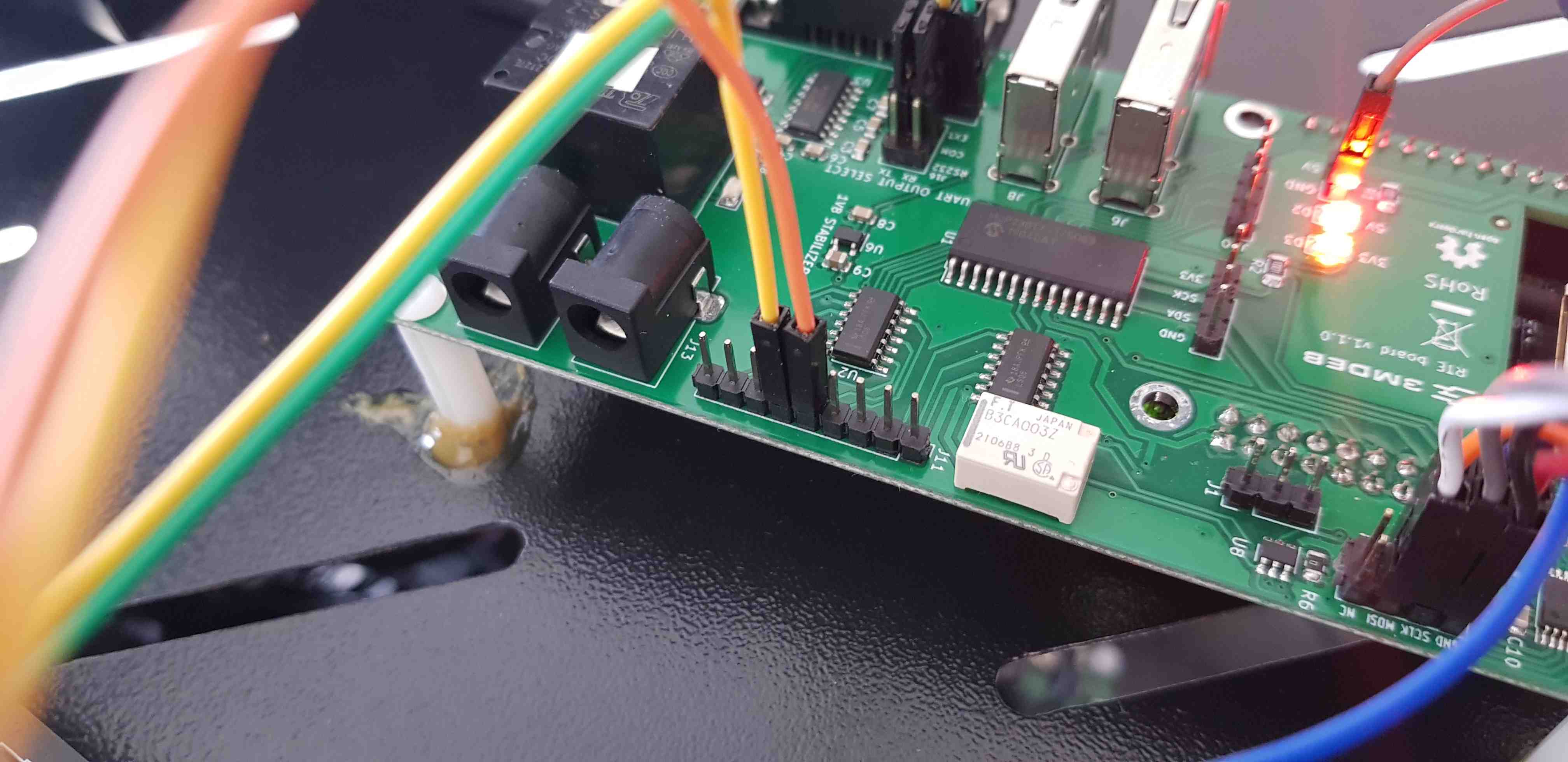
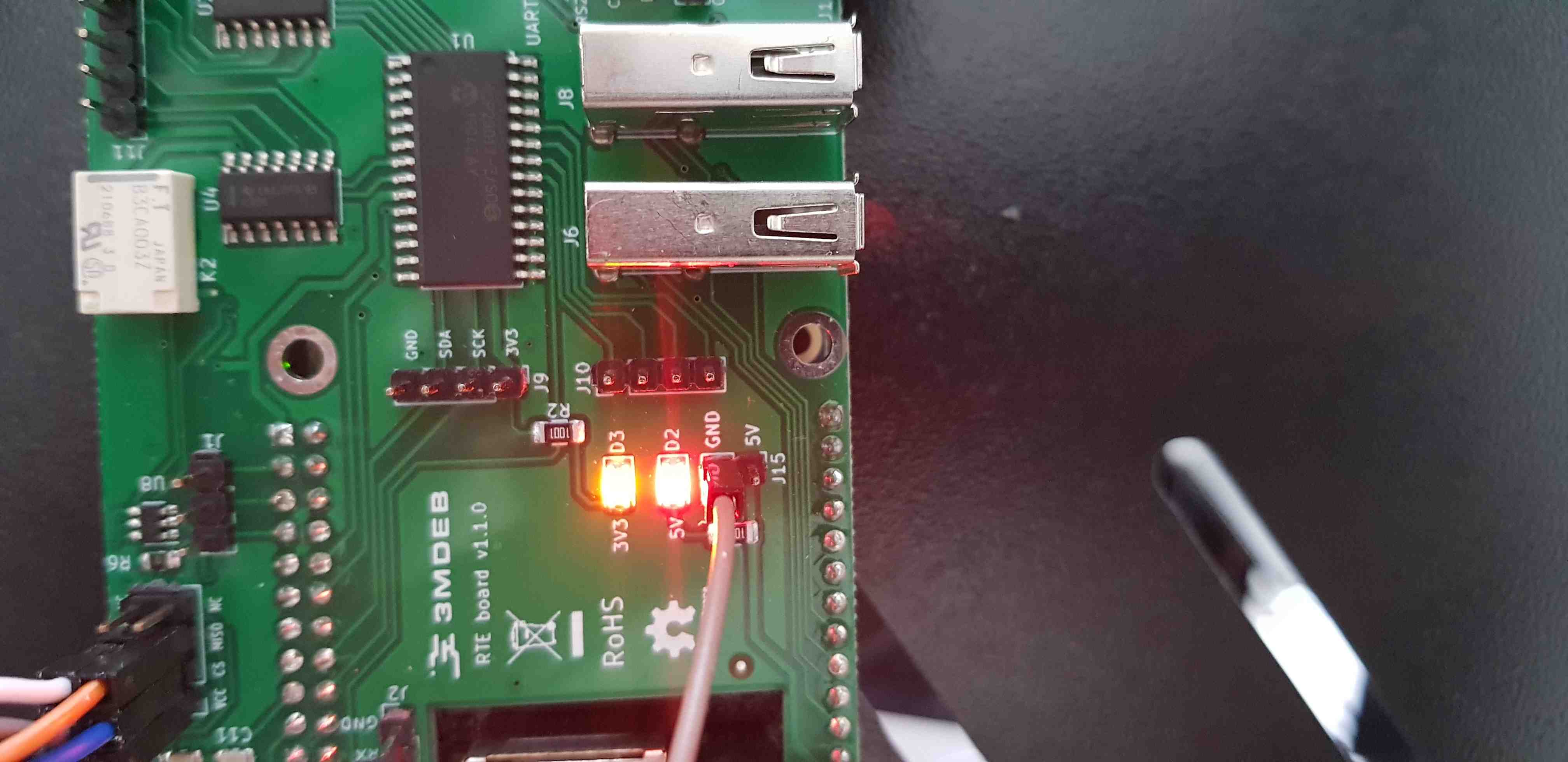
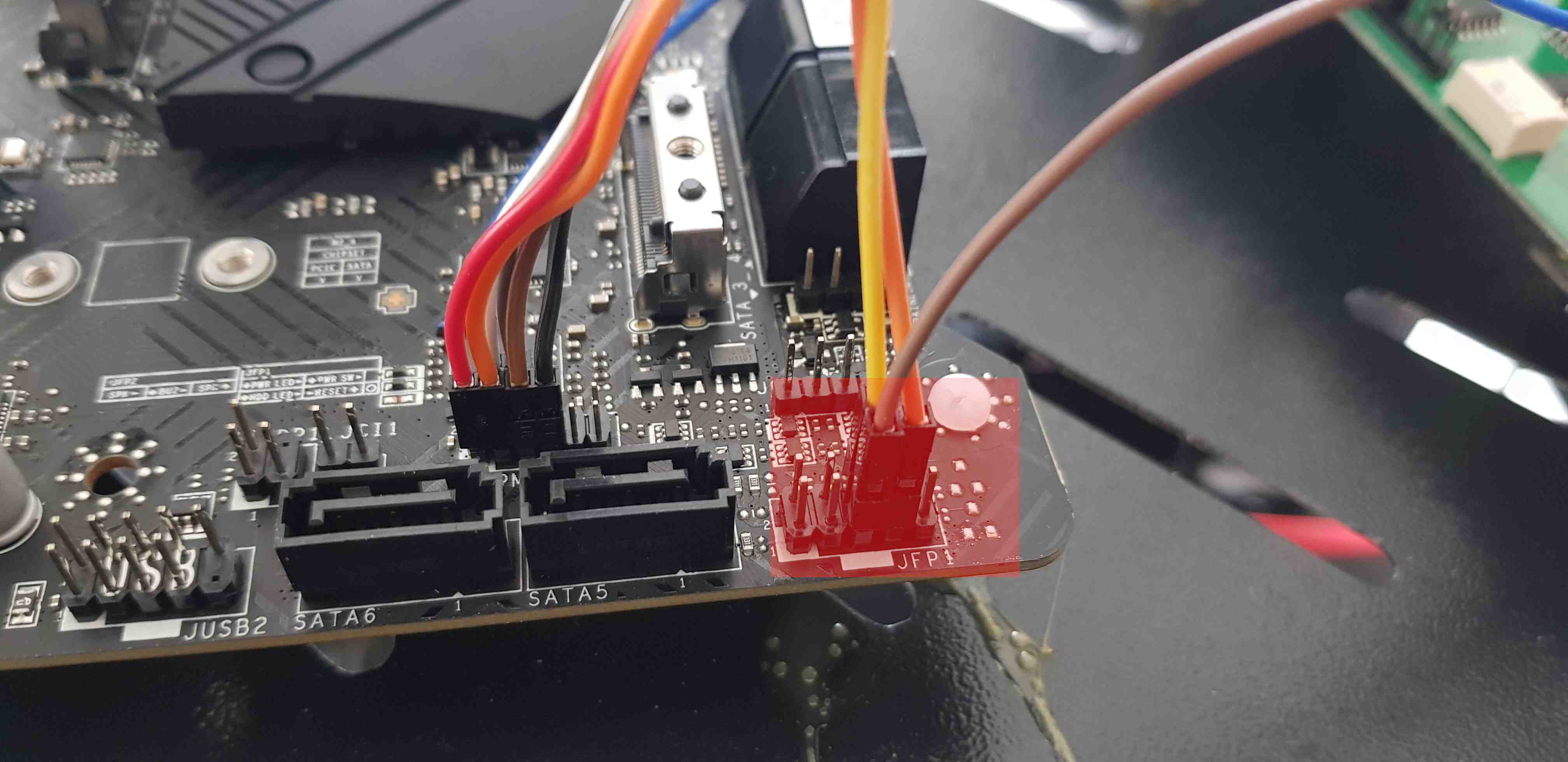
Connect the RTE J11 header to the platform JFP1 header as described in the table:
| RTE | Msi Z690 |
|---|---|
| J11 pin 9 | JFP1 pin 6 (PWR_ON) |
| J11 pin 8 | JFP1 pin 7 (RST) |
| J15 pin 1 (GND) | JFP1 pin 5 (GND) |
External flashing enabling
Without discrete TPM
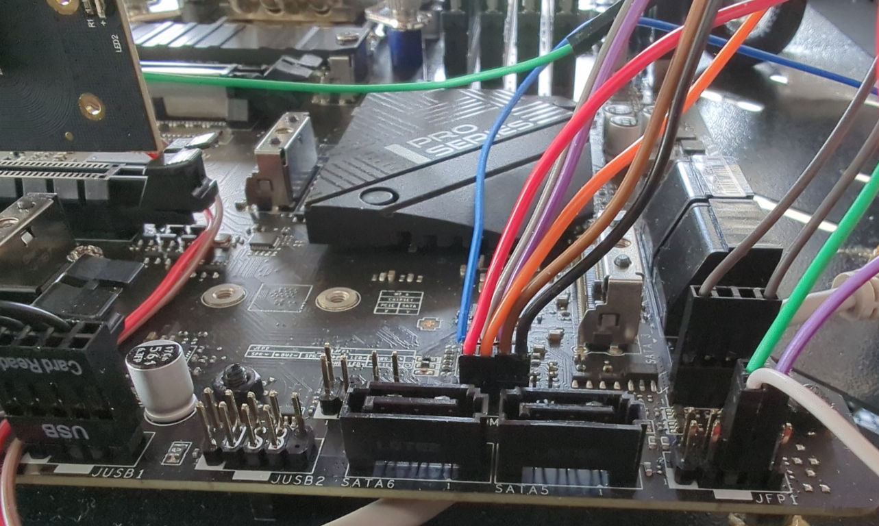
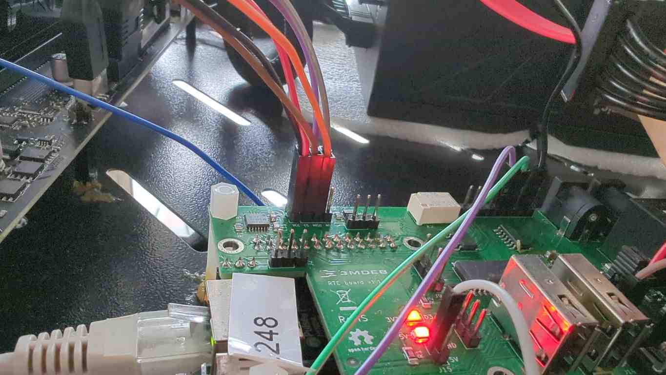
Connect the RTE SPI header to the platform as described in the table:
| RTE SPI header | MSI Z690-A |
|---|---|
| J7 pin 1 (Vcc) | JTPM1 pin 1 (SPI Power) |
| J7 pin 2 (GND) | JTPM1 pin 7 (GND) |
| J7 pin 3 (CS) | JTPM1 pin 5 (RESERVED / BIOS SPI CS pin) |
| J7 pin 4 (SCLK) | JTPM1 pin 6 (SPI Clock) |
| J7 pin 5 (MISO) | JTPM1 pin 3 (MISO) |
| J7 pin 6 (MOSI) | JTPM1 pin 4 (MOSI) |
Note: external access to the flash chip is possible only from the JTPM header. JTPM1 is a 2mm pitch header, you will need 2mm to 2.54mm female-female dupont wires to connect to RTE.
With discrete TPM
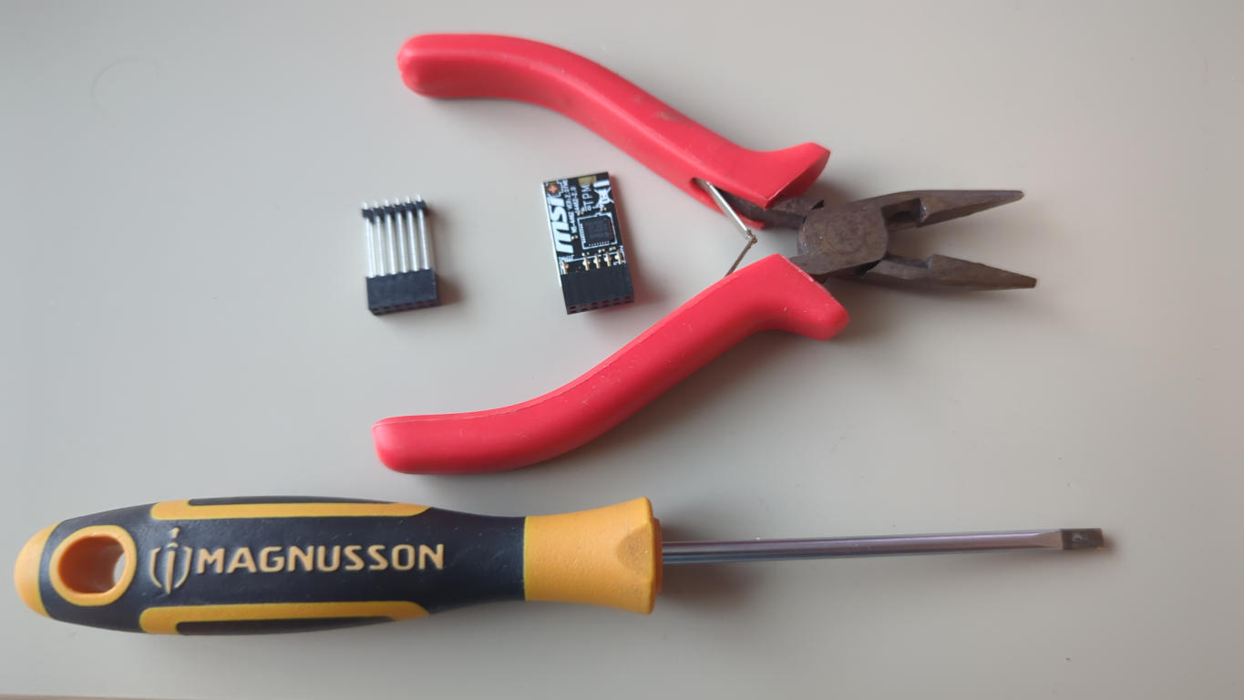
Alternative connection with TPM and external flashing requires some preparation before a TPM can flashing wires can be connected. You will need:
- flat screwdriver
- pliers
- MSI SPI TPM 2.0
- 6x test hook clips
- a 2mm pitch header 2x6 pin with long through pins
-
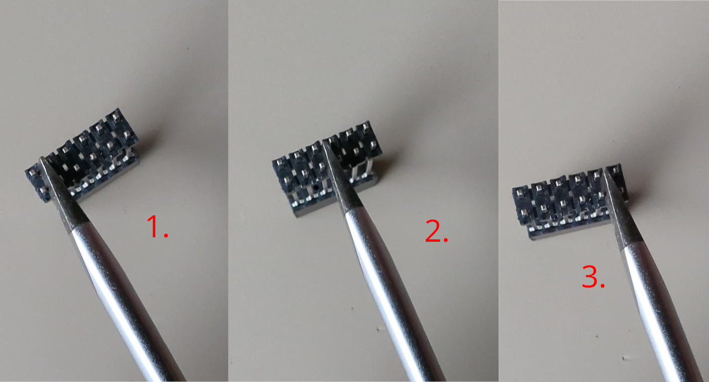
Push down the black stopper down. You may help yourself with a small flat screwdriver by creafully pushing it in the points 1, 2 and 3 shown in the picture below:
-
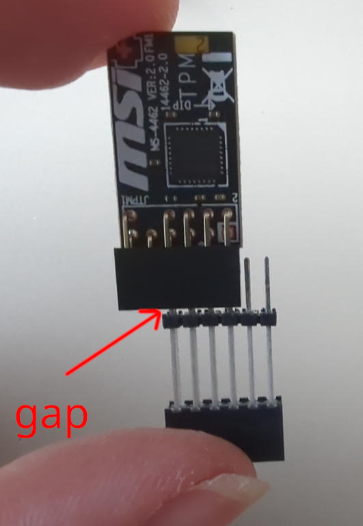
Repeat pushing it down until the TPM goes fully in, leaving a small gap between TPM connector and the header's black shield:
-
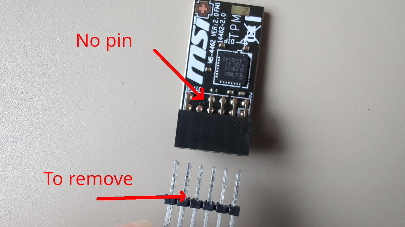
MSI TPM header has one "no-pin". Locate it on the TPM module and mark the pin on the header to be removed:
-
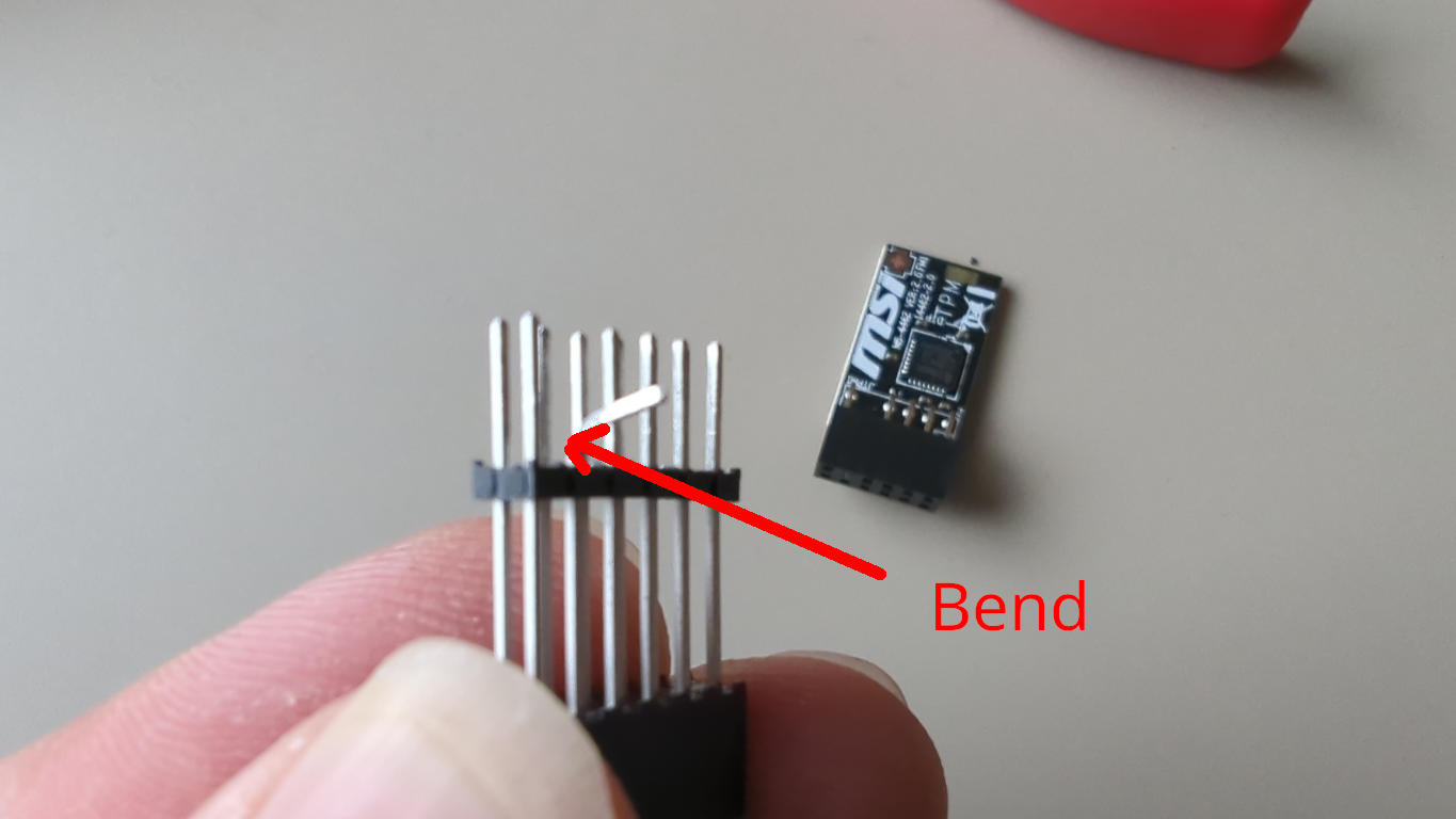
Bend the marked pin to be removed:
-
Carefully keep bending the marked pin forwards and backwards until it breaks:
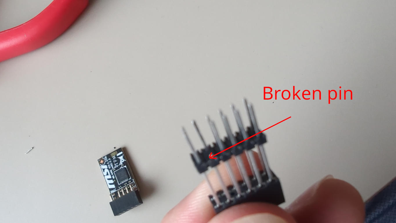
-
Put the TPM onto the header and push the black shield up so that the gap is removed:
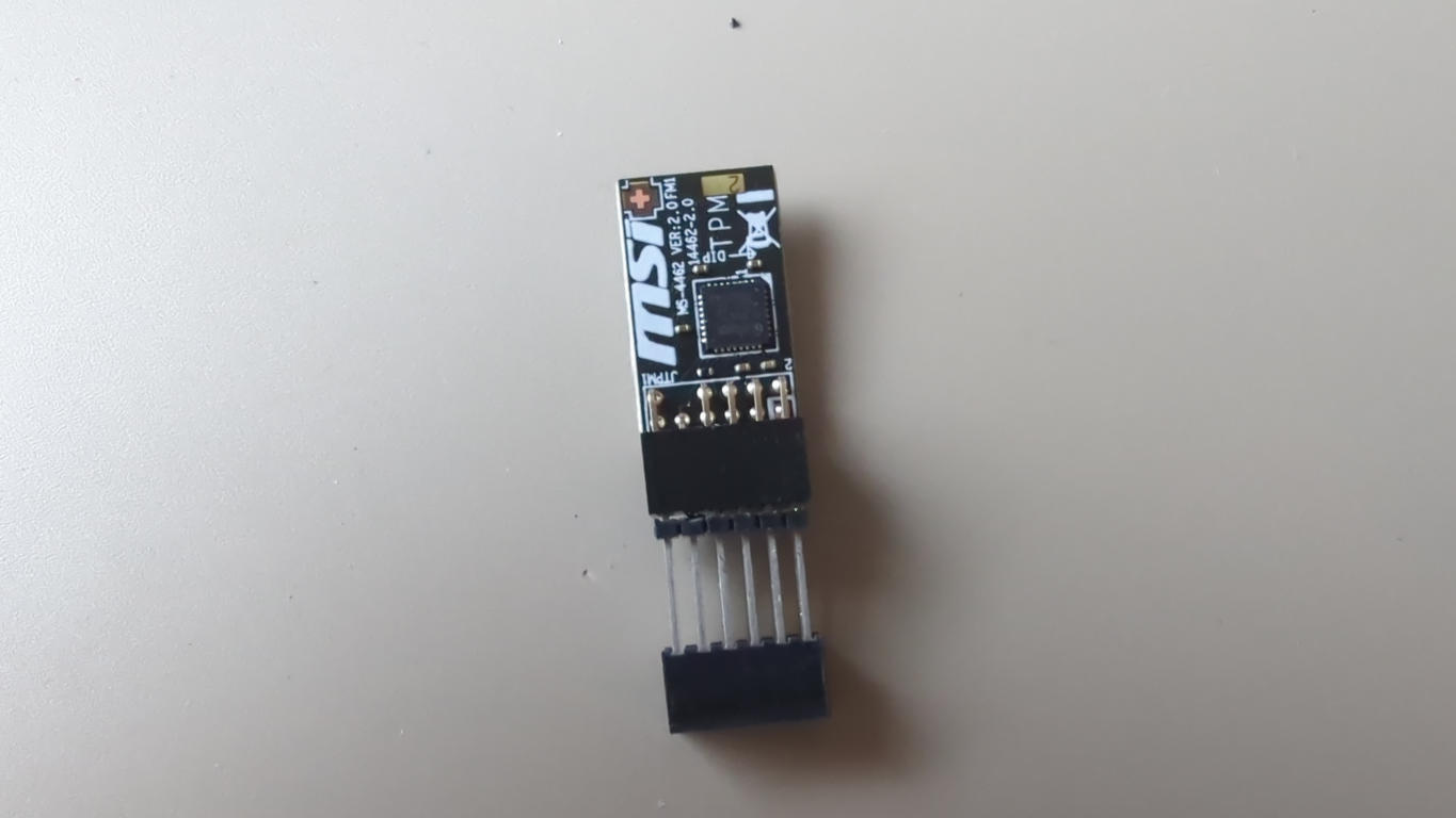
-
Connect the test hook clips to the header's legs so that it matches the JTPM1's SPI power, GND, BIOS SPI CS, SPI clock, MISO, MOSI:
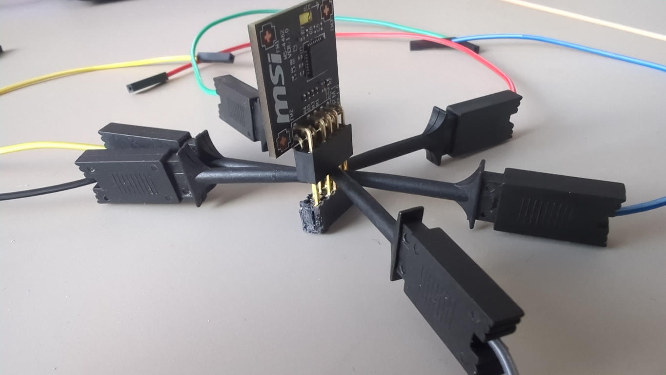
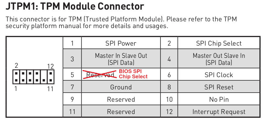
-
Connect such "spider" to the mainboard's JTPM1 header (remember to match the "no-pin: location).
-
Connect the femal pin side of the test hook clips to the RTE:
RTE SPI header MSI Z690-A J7 pin 1 (Vcc) JTPM1 pin 1 (SPI Power) J7 pin 2 (GND) JTPM1 pin 7 (GND) J7 pin 3 (CS) JTPM1 pin 5 (RESERVED / BIOS SPI CS pin) J7 pin 4 (SCLK) JTPM1 pin 6 (SPI Clock) J7 pin 5 (MISO) JTPM1 pin 3 (MISO) J7 pin 6 (MOSI) JTPM1 pin 4 (MOSI)
Device power status readout
Connect the RTE J1 header to the platform JFP1 header as shown in the picture below:
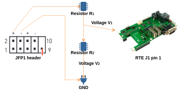
The values of R1, R2, V1 and V2 should meet the relationship according
to the formula R1/R2 = V2/V1. V1 cannot be greater than 3.3V (RTE property).
Complete Setup
After preparing all of the connections also three activities should be performed to enable all of the test stand features:
-
Connect Sonoff to the mains:
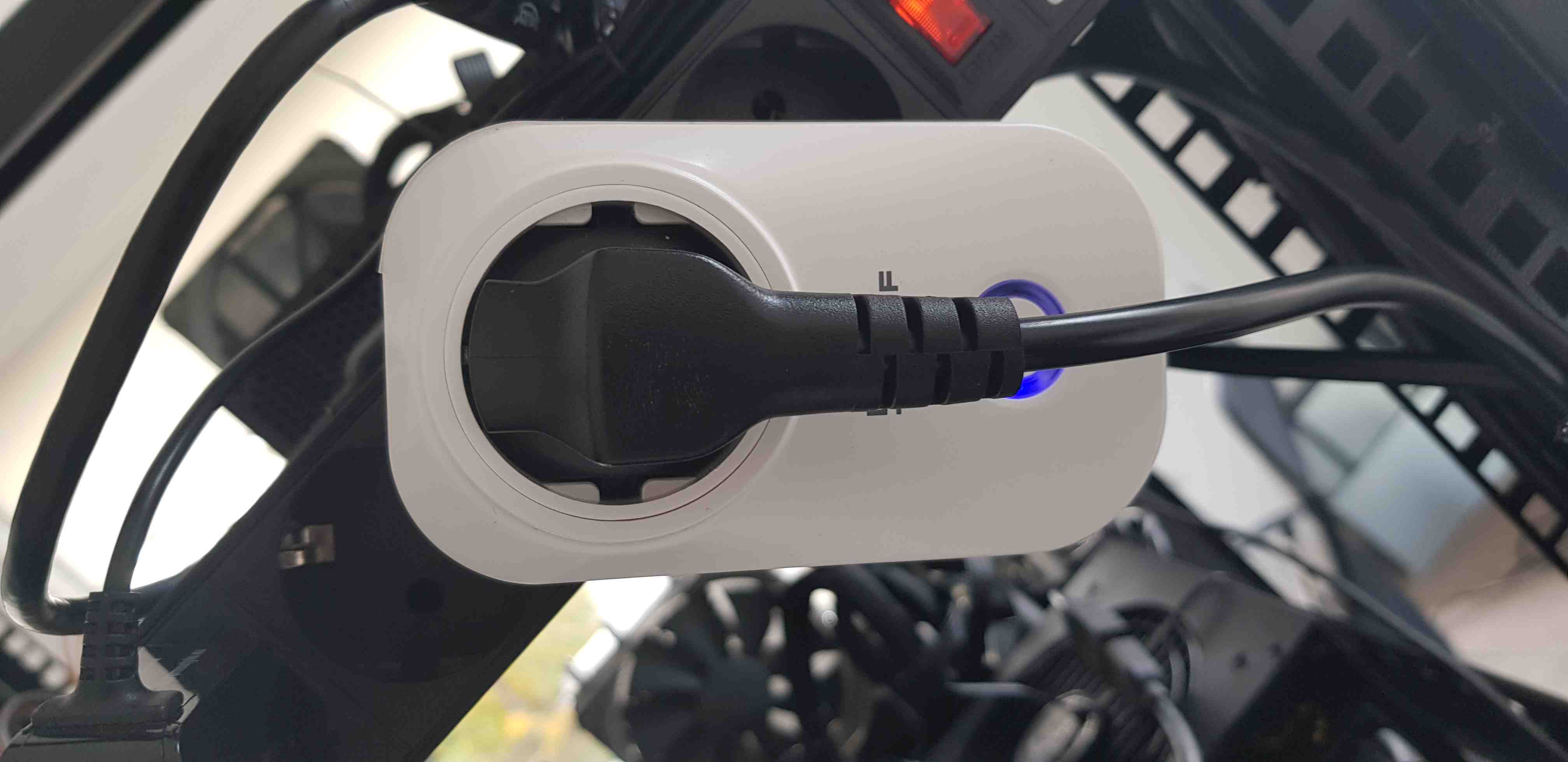
-
Connect the RTE to the Internet by using the Ethernet cable.
- Connect the RTE to the mains by using the microUSB 5 V/2 A power supply.
Complete setup should looks as follows:
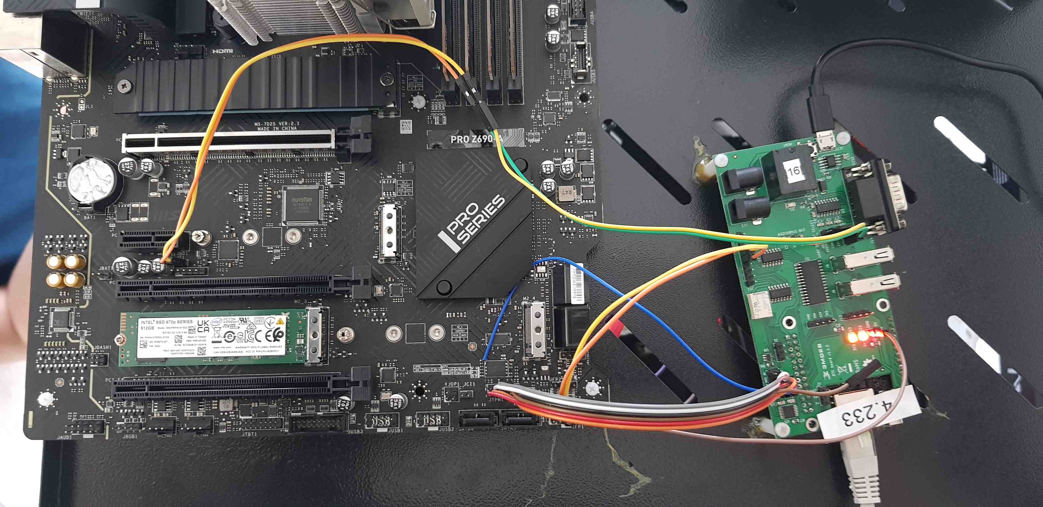
Theory of operation
The following sections describe how to use all of the enabled features:
- serial connection to the platform,
- controlling power supply,
- enabling basic power actions with the platform (power off/power on/reset),
- external flashing with the RTE,
- device power status readout.
Serial connection
The method of setting and using serial connection is described in the Serial connection guide.
Power supply controlling
Power supply controlling (in this case: controlling the state of Sonoff)
should be performed based on the sonoff.sh script implemented in meta-rte
(OS image dedicated to the RTE platform).
Note, that before using the above-mentioned script, it should be modified and
SONOFF_IPparameter should be set in accordance with obtained Sonoff IP address.
To perform basic power operations use the below-described commands:
-
Turn on the power supply:
./sonoff on -
Turn off the power supply:
./sonoff on
Basic power operations
Basic power operations should be performed based on the rte_ctrl script
implemented in meta-rte (OS image dedicated to the RTE platform). To perform
basic power operations use the below-described commands:
-
Turn on the platform:
rte_ctrl pon -
Turn off the platform:
rte_ctrl poff -
Reset the platform:
rte_ctrl reset
Note, that in order for the above commands to work properly, the platform should be powered up: both Sonoff and the power supply must be turned on.
External flashing
The external flashing procedure should be performed based on the scripts implemented on the RTE platform. To perform the flashing operation reproduce, the below-described steps:
-
By using
scpput the requested Dasharo file to the RTE:scp <path_to_firmware>/<firmware_file> root@<RTE_IP>:/tmp/coreboot.romWhere:
path_to_firmware- path to firmware, which should send to RTE,firmware_file- the name of the firmware file, which should be sent to RTE,RTE_IP- IP address of the connected RTE.
-
Login to RTE via
sshorminicom. -
Read the flash chip by executing the following command on RTE:
./flash.sh read tmp/dump.rom -
If the reading was successful, the output from the command above should contain the phrase
Verifying flash... VERIFIED. -
Write the flash chip by executing the following command on RTE:
./flash.sh write /tmp/coreboot.romDo not interrupt the flashing procedure in any way (especially by changing connections). It may cause hardware damage!
-
If the reading was successful, the output from the command above should contain the phrase
Verifying flash... VERIFIED.
Device power status readout
To read the current power status use the following command:
cat /sys/class/gpio/gpio12/value
Example output:
1means that the platform is turned on.0means that the platform is turned off.
USB devices
USB 3.x (blue) ports in the 4 port column of rear I/O have an issue where if they are populated during boot, the boot process will slow to a crawl. Do not populate these ports on boards installed in the lab.