Laboratory stand dedicated to Odroid-H4 platforms assembly guide
Introduction
This document describes platform-specific details for assembling Odroid H4 testing stands. Use this document as reference while going through Generic Testing Stand Setup
Prerequisites
The below table contains platform-specific information about all elements which are needed to create testing stands for Odroid H4.
- RTE v1.1.0
- RTE power supply 5V 2A Micro-USB
- 11x standard female-female connection wire 2.54 mm raster
- Pomona 8-pin SOIC clip
- 2x RJ45 cable: 1 for RTE and 1 for the platform
- NVMe disk
- eMMC module for ODROID
For netcard setup additionally:
- 1x female 2.54 mm raster connection wire with a probe hook
- 2x RJ45 cable: short patchcords for the netcard ports
- SATA SSD 2.5'' instead of NVMe disk
- SSD disk adapter to SATA+power connector
If you have a proper SATA cable and power cable for the dedicated connectors on ODROID, use them instead.

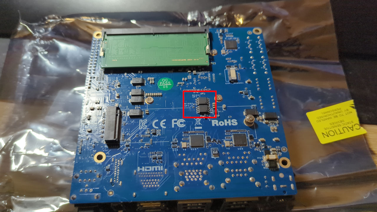
External flashing enabling
Connect the RTE SPI header to the platform using the 2.54 mm female-female
wires and Pomona as shown in Generic testing stand setup
to the flash chip on the bottom of your platform:
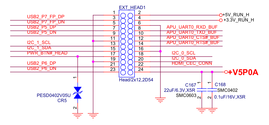
Serial connection
The method of setting and using serial connection is described in the Serial connection guide. In this case, you will need to enable UART port and connect it to the pins 6, 8 and 10 of ODROID's Peripheral Expansion Header using 2.54 mm female-female wires.
| RTE J18 | Odroid H4 EXPANSION HEADER |
|---|---|
| J18 pin 1 (TX) | pin 8 APU_UART_RXD_BUF |
| J18 pin 2 (RX) | pin 10 APU_UART_TXD_BUF |
| J18 pin 3 (GND) | pin 6 GND |
Netcard specific setup
When assembling a netcard in the M.2 NVMe slot, ensure the standoffs are mounted first before mounting the netcard into ODROID. Then use a screw to secure the netcard connection:

After assembling the netcard, connect 2x RJ45 short patchcords to ports 1-2 and 3-4. The automated validatio nwill use that connection to verify that Ethernet ports are functional and meet performance criteria.

When a netcard is present in the M.2 NVMe slot, it is not possible to have an NVMe disk anymore. Thus one needs to connect an SATA disk. ODROID H4+ and H4 Ultra have 4 SATA slots, which can be used as an alternative storage. Connect the SATA cable to one of the SATA connectors. Connect the black-red wire pair for SATA power to the pins 1 and 2 of ODROID's Peripheral Expansion Header. note that the red-black wire pair has to be isolated at the end, because the exposes metal surfaces on the connector may touch the neighboring pins of the ODROID's Peripheral Expansion Header.
If you have a proper SATA cable and power cable for the dedicated connectors on ODROID, use them instead.

| SATA power cable | Odroid H4 EXPANSION HEADER |
|---|---|
| black | pin 1 GND |
| read | pin 2 +5V_RUN_H |
Power LED connection
The power LED indication is used often in the validation suites to check the power state of the platform. Connect RTE J10 pin 1 with the pins 4 of ODROID's Peripheral Expansion Header using 2.54 mm female-female wire. It allows the RTE to read the power LED state.
| RTE J10 | Odroid H4 EXPANSION HEADER |
|---|---|
| J18 pin 1 | pin 4 +3.3V_RUN_H |
For netcard setup use the wire with probe hook, because the SATA power cable has a thick connector, which prevents standard 2.54mm wire to be connected:
If you have a proper SATA cable and power cable for the dedicated connectors on ODROID, use regular 2.54mm wire instead.

Power button connection
The platform features PWR pin for powering on and shutting down the device.
Connect two wires to pins 17 (PWR_BTN) and 9 (GND) on the Odroids' GPIO
header. The pinout can be found
here.
The PWR_BTN must be connected to pin 6 on RTE J11 header, and the GND
must be connected to RTE pin 1 on J15 header. This has been summarized in
the table below:
| RTE J11 | RTE J15 | Odroid H4 EXPANSION HEADER |
|---|---|---|
pin 6 |
-- | pin 17 (PWR_BUTTON) |
| -- | pin 1 |
pin 19 (GND) |
Note: Odroid does not feature RESET pin on onboard header.
Preparing custom cables for power supply controlling
The Odroid h4 dc plug/socket specification is 5.5mm x 2.1mm. The RTE, on
the other hand, has 5.5mm x 2.5mm ports. This means if you attempt to connect
RTE to Odroid with RTE compatible cable, the power won't be flowing as there will
be 0.4mm gap in the connector itself. This is why a custom set of cables
is needed.
You'll need to either create (solder) or buy a following set of cables:
5.5mmx2.5mmmale plug -5.5mmx2.1mmfemale connector.5.5mmx2.5mmmale plug -5.5mmx2.1mmmale plug.
Custom set of cables has been showcased in the pictures below:


To connect the cables:
- plug
5.5mmx2.5mmmale plugs into the RTE (order does not matter), - plug the Odroid power brick into the female end on one of the cables,
- plug the
5.5mmx2.1mmmale plug into the Odroid dc port.
Theory of operation
The following sections describe how to use all of the enabled features:
- serial connection to the platform,
- controlling power supply,
- enabling basic power actions with the platform (power off/power on),
- external flashing with the RTE.
Power supply controlling
Power supply controlling is performed with the relay module on RTE
connected to one of RTE GPIOs. Power operation should be performed using
the rte_ctrl script implemented in meta-rte (OS image dedicated to the
RTE platform).
To toggle the power supply use the below command:
rte_ctrl rel
Basic power operations
Basic power operations should be performed based on the rte_ctrl script
implemented in meta-rte (OS image dedicated to the RTE platform). To perform
basic power operations use the below-described commands:
-
Turn on the platform:
rte_ctrl pon -
Turn off the platform:
rte_ctrl poff
Note, that in order for the above commands to work properly, the platform should be powered up: both RTE Relay and the power supply must be connected and turned on.
External flashing
The external flashing procedure should be performed based on the scripts implemented on the RTE platform. To perform the flashing operation reproduce, the below-described steps:
Important
It is recommended to detect the chip with the DC jack power cable disconnected from the Odroid. If the chip is successfully detected, you can reconnect the DC power jack and proceed with your task. If the chip fails to detect after reconnecting the power, you may need to attach an additional grounding cable to the RTE. This additional grounding is not always necessary, but it can resolve detection issues if they arise.
-
First run the flashrom command on RTE to check if the flash is detected by following the first three steps from this guide , this chip requires 3.3V.
-
Next check if the pomona is connected properly.
flashrom -p linux_spi:dev=/dev/spidev1.0,spispeed=16000 -
By using
scpput the requested Dasharo file to the RTE:scp <path_to_firmware>/<firmware_file> root@<RTE_IP>:/tmp/coreboot.romWhere:
path_to_firmware- path to firmware, which should send to RTE,firmware_file- the name of the firmware file, which should be sent to RTE,RTE_IP- IP address of the connected RTE.
-
Login to RTE via
sshorminicom. -
Write the flash chip by executing the following command on RTE:
flashrom -p linux_spi:dev=/dev/spidev1.0,spispeed=16000 -w /tmp/coreboot.romDo not interrupt the flashing procedure in any way (especially by changing connections). It may cause hardware damage!
-
If the writing was successful, the output from the command above should contain the phrase
Verifying flash... VERIFIED.
USB devices
Since some issues with USB controllers may only happen on selected USB ports, it's important to plug in USB devices to all 4 USB ports of the board.
NVMe disk
Connect NVMe disk to the bottom M.2 slot for SSD. The disk will serve as main storage for operating systems.
eMMC module
Plug ODROID eMMC module to the eMMC connector on board. eMMC is optional storage for operating systems but may be used in automated testing to validate eMMC functionality.
