Recovery
Intro
The following documentation describes the process of recovering hardware from the brick state using an RTE and Dasharo open-source firmware.
Flashing via BMC
- Ensure the board is soft powered off and BMC active (PSU connected and powered).
- Log in to BMC admin panel with unique credentials for your platform. Login
is
adminand password is unique , present on a sticker on the board box. - Navigate to
Maintenance->Firmware Update
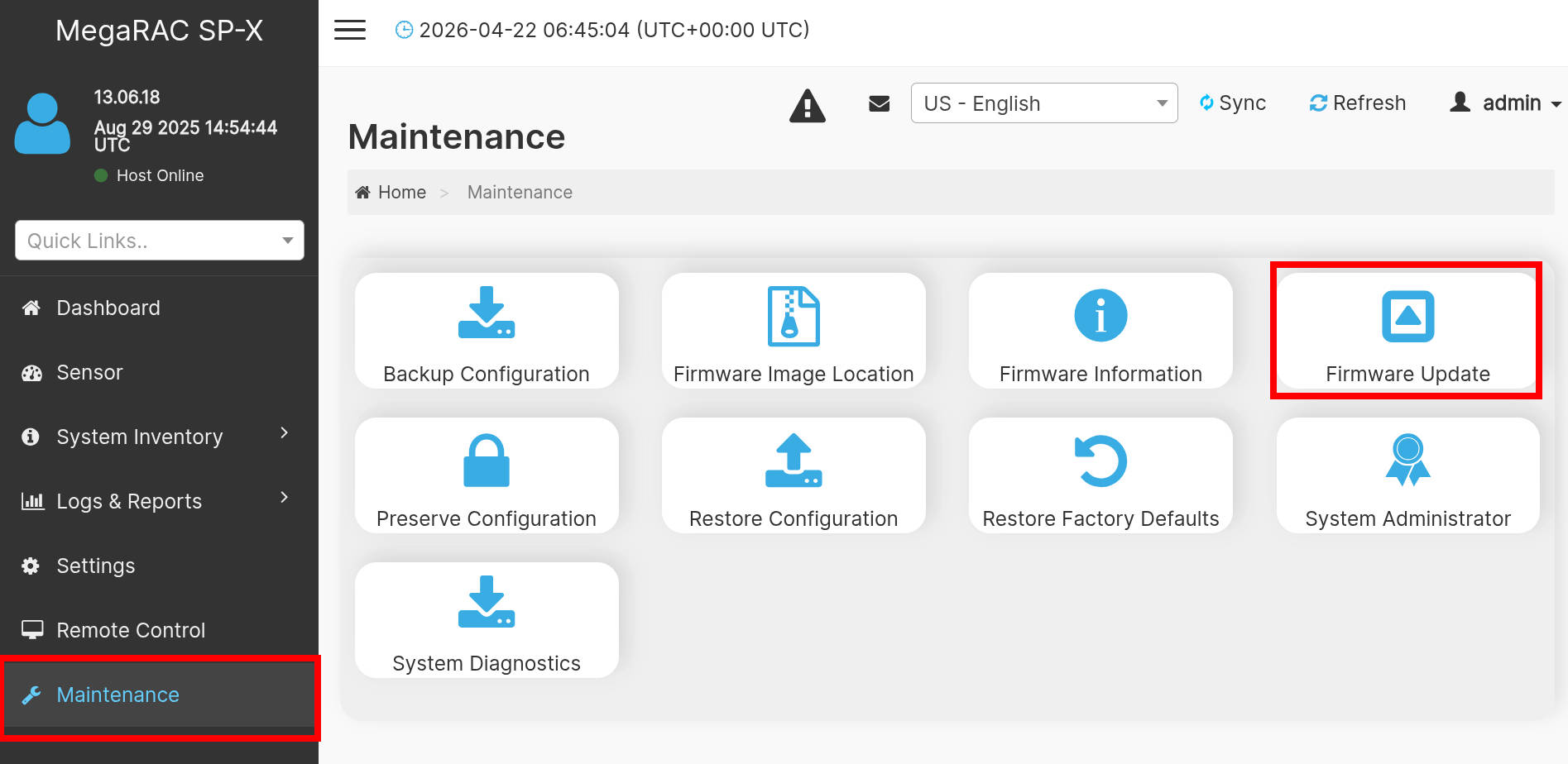
- In the file selection field, press the file selection button and find the
gigabyte_mz33_ar1_v0.9.x.rbufile on your host device. - Click to proceed with flashing and confirm.
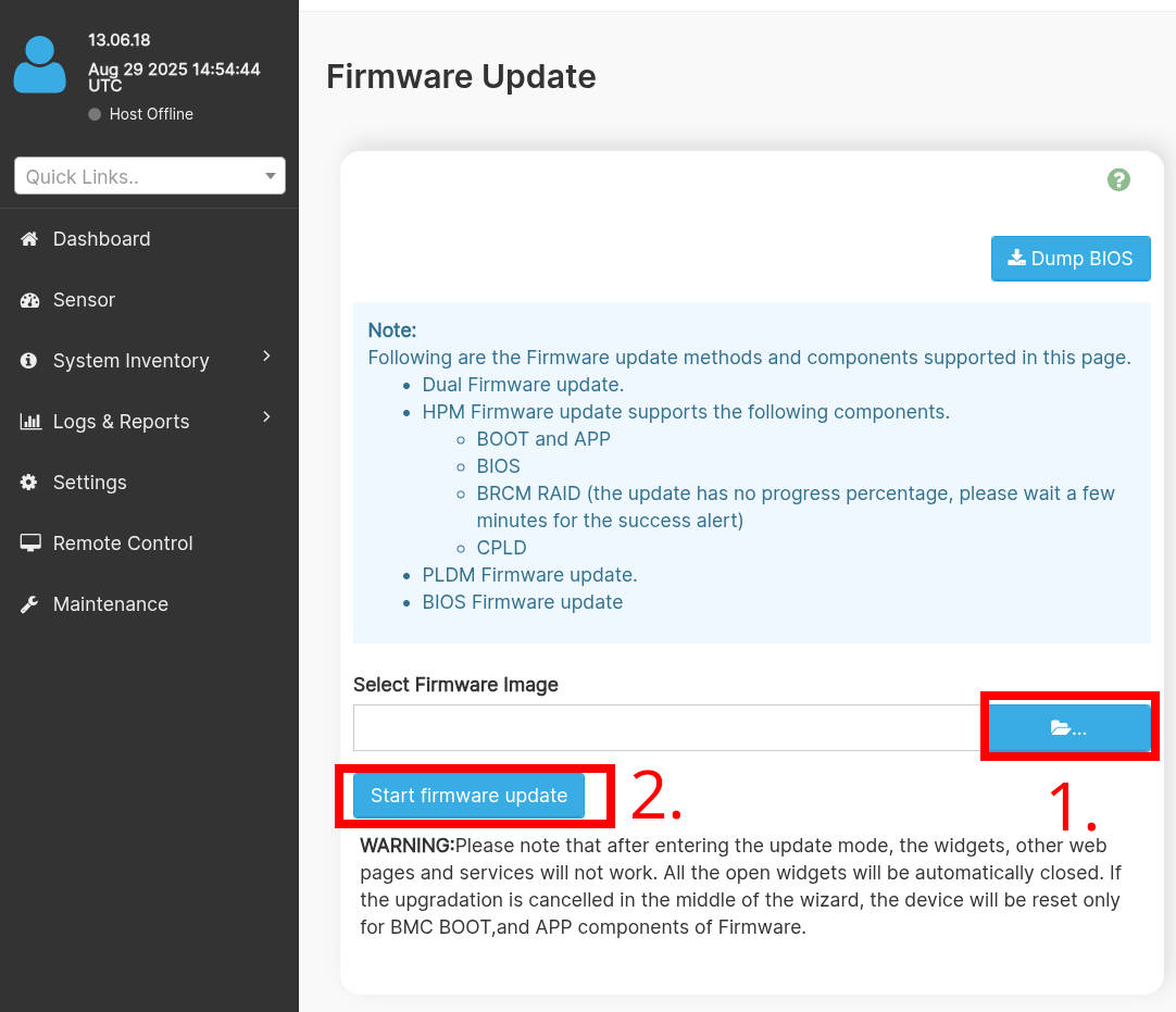
- Wait until the process completes and then power on the board.
External flashing
The external programming and recovery from bricks caused by Dasharo can be achieved by flashing o
Prerequisites
- Prepared RTE
- 6x female-female wire cables
- pomona SOIC8 clip
Connections
To prepare the stand for flashing follow the steps described in the Generic test stand setup
Firmware flashing
To flash firmware follow the steps described below:
- Login to RTE via
sshorminicom. - Turn on the platform by connecting the power supply.
- Wait at least 5 seconds.
- Turn off the platform by using the power button.
- Wait at least 3 seconds.
-
Set the proper state of the SPI by using the following commands on RTE:
# set SPI Vcc to 3.3V
echo 1 > /sys/class/gpio/gpio405/value
# SPI Vcc on
echo 1 > /sys/class/gpio/gpio406/value
# SPI lines ON
echo 1 > /sys/class/gpio/gpio404/value
Starting with RTE distro v0.8.x the GPIOS are 517, 518, 516.
-
Wait at least 2 seconds.
- Disconnect the power supply from the platform.
- Wait at least 2 seconds.
-
Check if the flash chip is connected properly
flashrom -p linux_spi:dev=/dev/spidev1.0,spispeed=16000 -
Flash the platform by using the following command:
flashrom -p linux_spi:dev=/dev/spidev1.0,spispeed=16000 \
    -w [path_to_binary]
The board sinks too much current which results in SPI Vcc to drop below an acceptable level when writing to flash. Reads are reliable, but write often fail. When PSU is off, the voltage on SPI chip is 2.5V-2.6V only from RTE. Sometimes it happens to go smoothly, but most of the time not. Using CH341A is more reliable, but leaves VCC always connected to the board, which tends to put the board in a limbo state. Recovering from such limbo requires disconnecting all power sources from the board (both PSU and CH341A). However, with OSFV cli the writes are somehow reliable, so it is recommended to use the utility.
-
Change back the state of the SPI by using the following commands:
echo 0 > /sys/class/gpio/gpio404/value
echo 0 > /sys/class/gpio/gpio405/value
echo 0 > /sys/class/gpio/gpio406/value
Starting with RTE distro v0.8.x the GPIOS are 516, 517, 518.
-
Turn on the platform by connecting the power supply.
The AMD board take longer to boot due to memory training happening on PSP side. Thus the first signs of life from open-source firmware may appear even after a couple of minutes (depends on amount of populated RAM).
Prerequisites
- CH341a USB to SPI programmer
- 6x female-female wire cables
- pomona SOIC8 clip
Connections
- Connect pomona SOIC8 clip to the CH341a programmer.
- Clip on the BIOS flash chip on the board.
Firmware flashing
To flash firmware follow the steps described below:
- Disconnect the power supply from the platform.
- Wait at least 2 seconds.
-
Check if the flash chip is connected properly
flashrom -p ch341a_spi -
Flash the platform by using the following command:
flashrom -p ch341a_spi -w [path_to_binary] -
Take off the pomona clip from the chip.
- Turn on the platform by connecting the power supply.
The AMD board take longer to boot due to memory training happening on PSP side. Thus the first signs of life from open-source firmware may appear even after a couple of minutes (depends on amount of populated RAM).