Presale device preparation and validation
Introduction
This document describes the preparation (assembly, flashing and verification) procedure of the ASRock SPC741D8 with specified components in requirements.
Requirements
| Part | Model Name | Image |
|---|---|---|
| Motherboard | ASRock SPC741D8 | 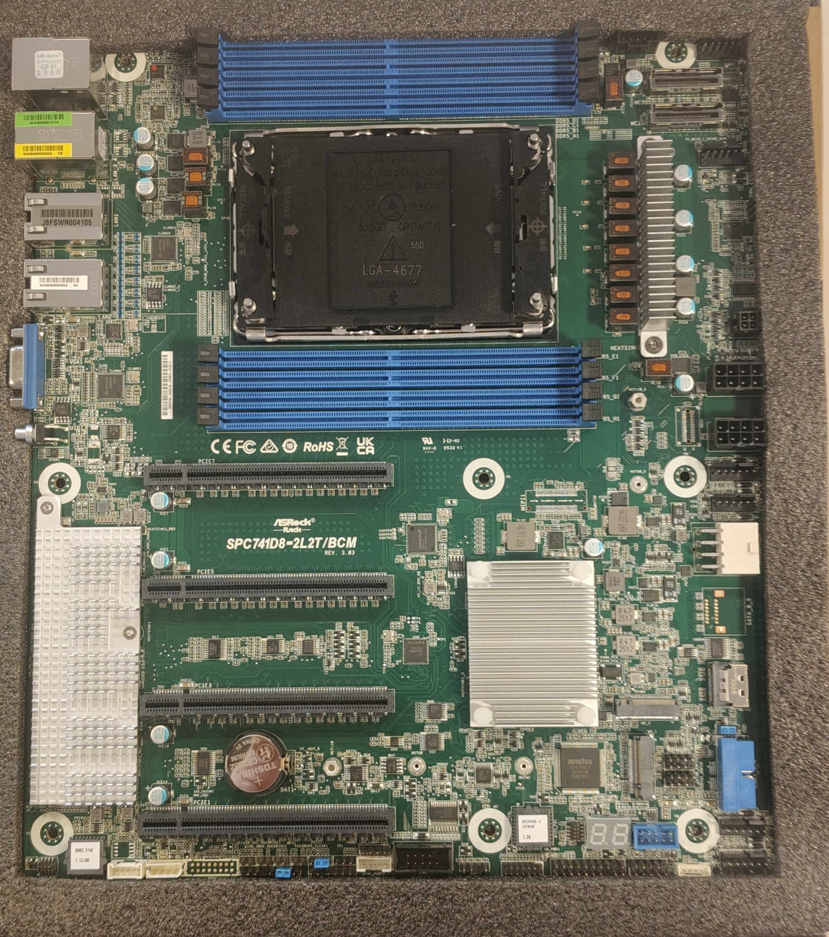 |
| CPU | Intel Xeon Silver 4410Y | 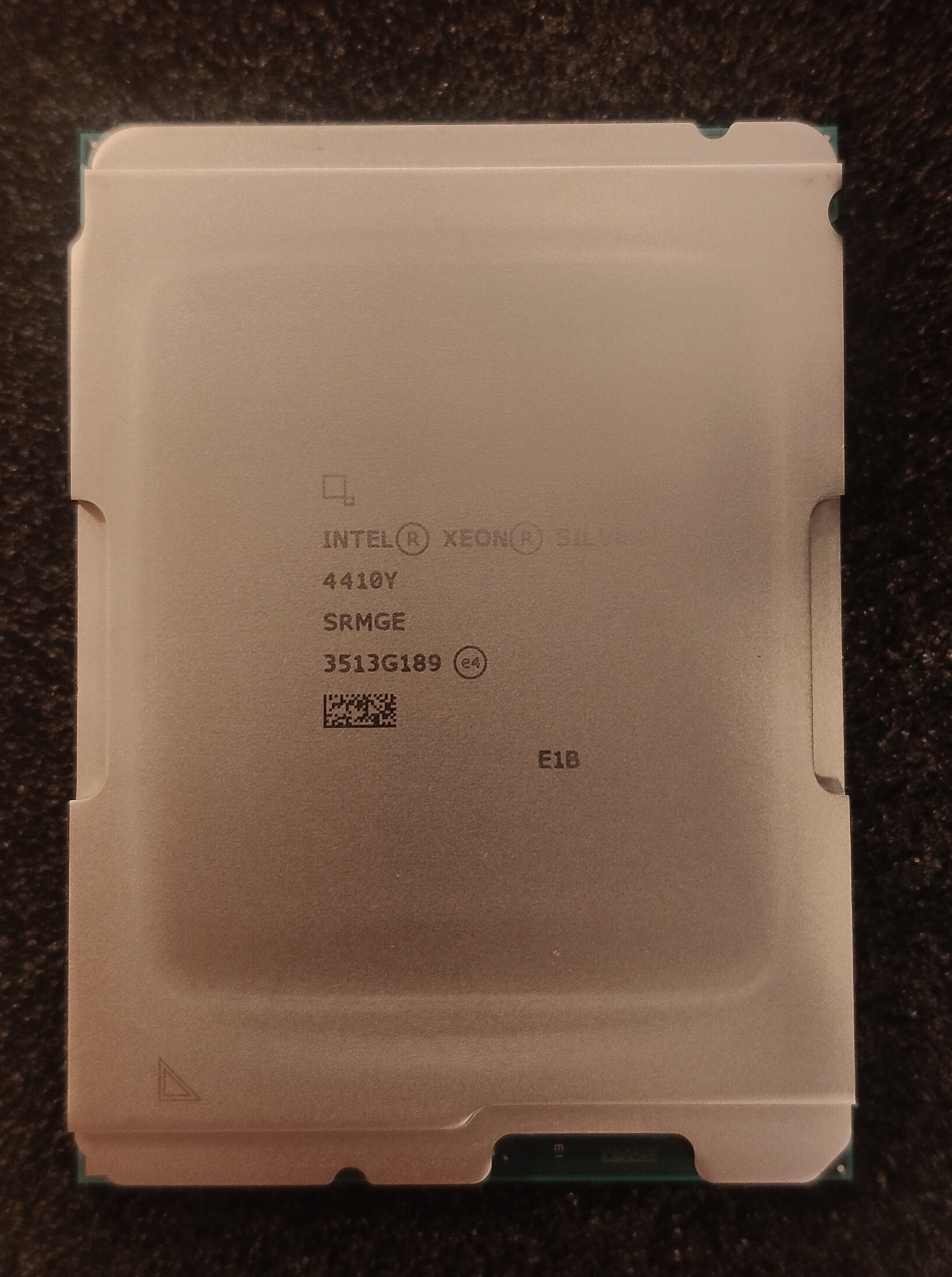 |
| Cooling | Arctic Freezer 4U-M | 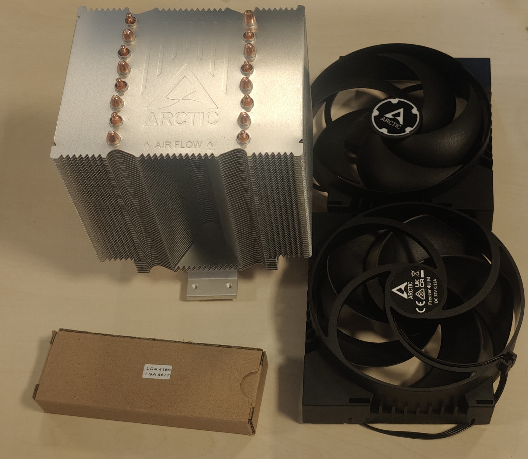 |
| RAM | Kingston 16GB DDR5 ECC KSM48R40BS8KMM-16HMR | 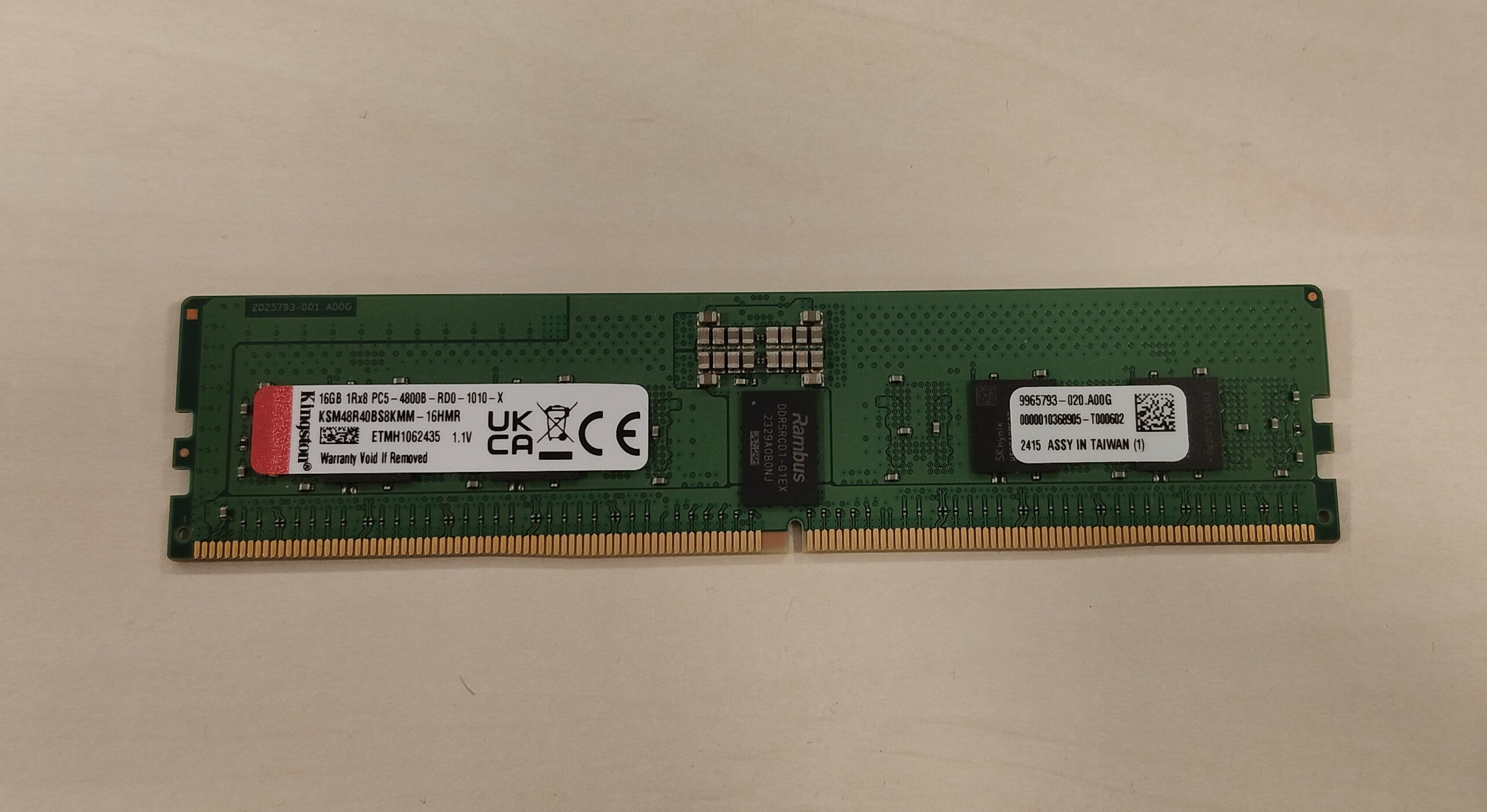 |
| Power Supply | Seasonic Vertex GX 850W 80 Plus Gold | 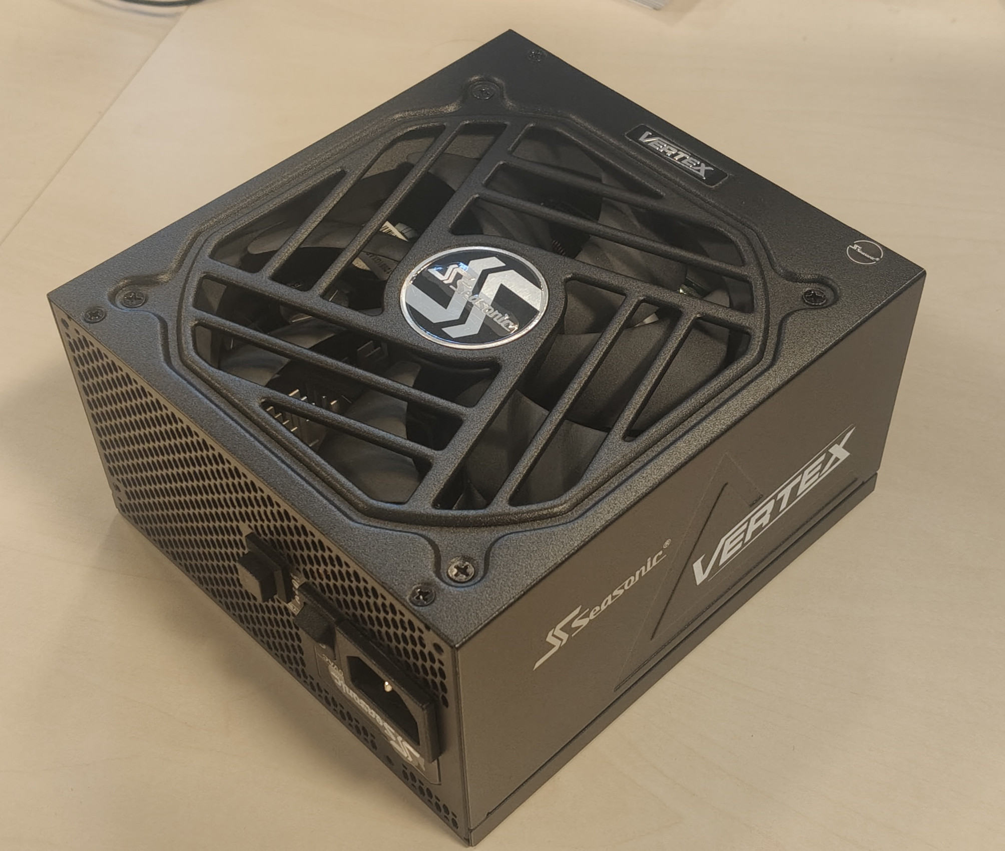 |
| Storage | SSD Kingston KC3000 512 GB M.2 2280 NVMe | 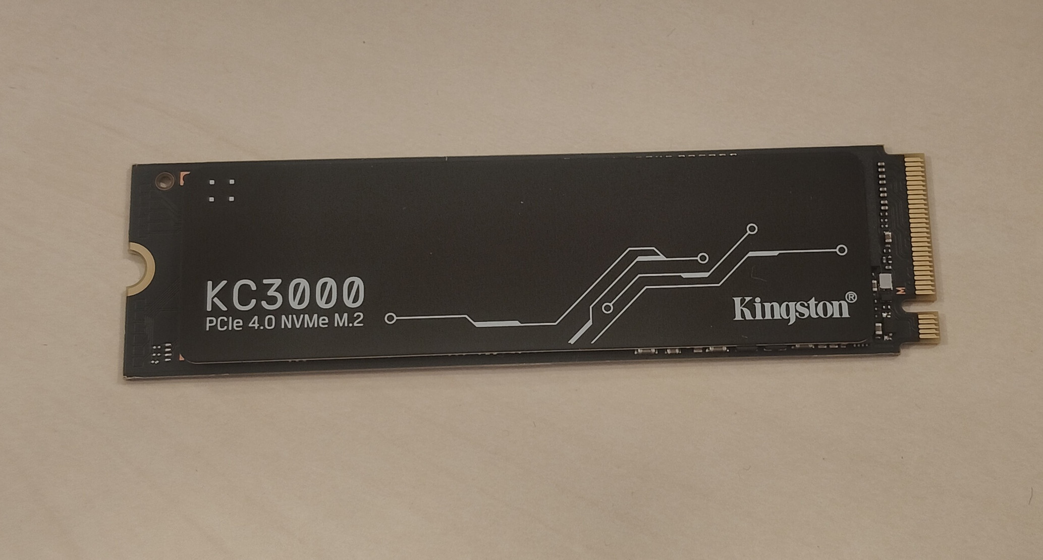 |
| Enclosure | SilverStone RM42-502 4U Rack Chassis | 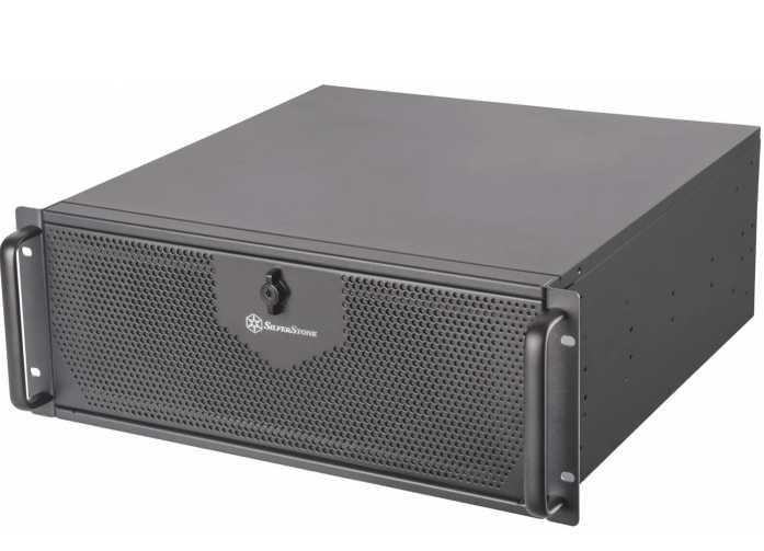 |
| TPM | ASRock TPM-SPI Module | 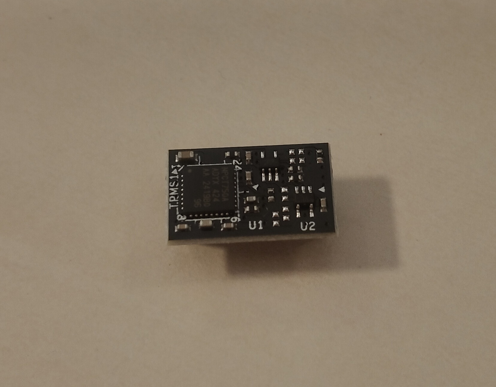 |
Additionally, you will need a screwdriver with bits P1, T30, and small pliers. Remember to make all connections with the grounding strap.
Device assembly
Full set assembly
The section below describes the procedure for the complete assembly of the working station.
-
Place the motherboard in front of you. This is the component with which most operations will be performed. It’s best to put something soft under the board to avoid damage during RAM installation and other steps.
-
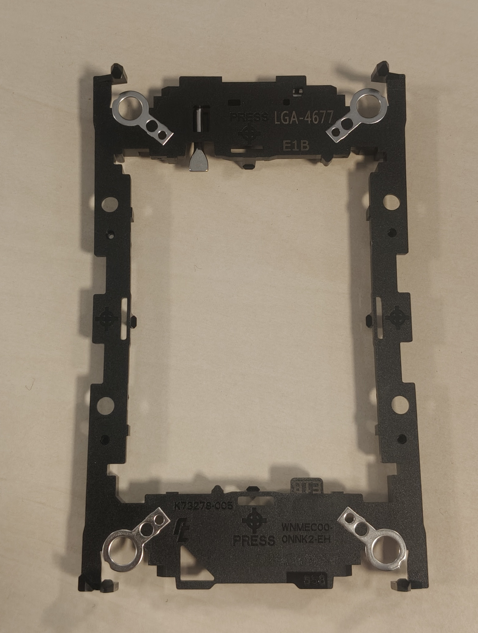
In the motherboard box, find the CPU bracket marked "E1B".
-
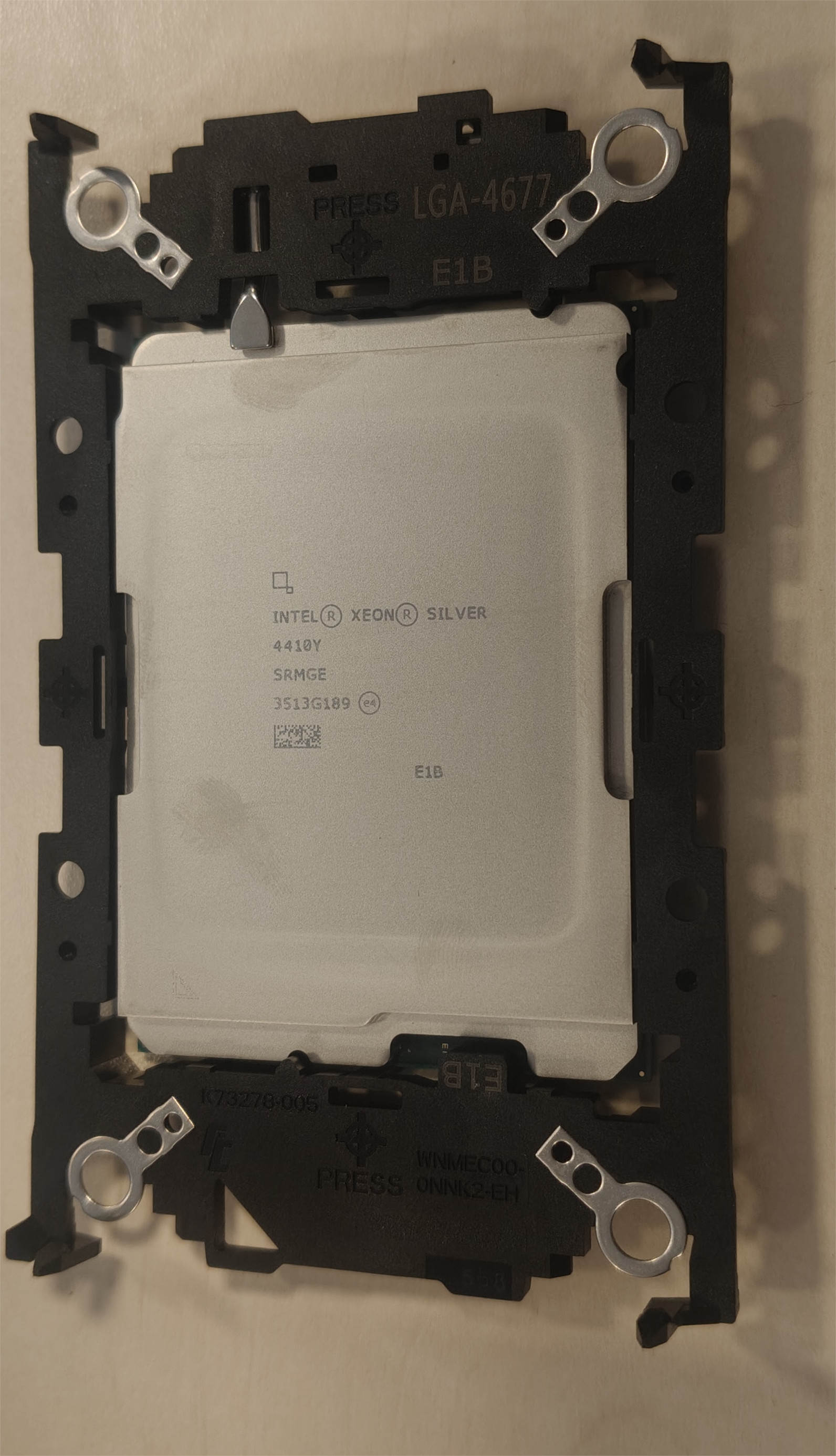
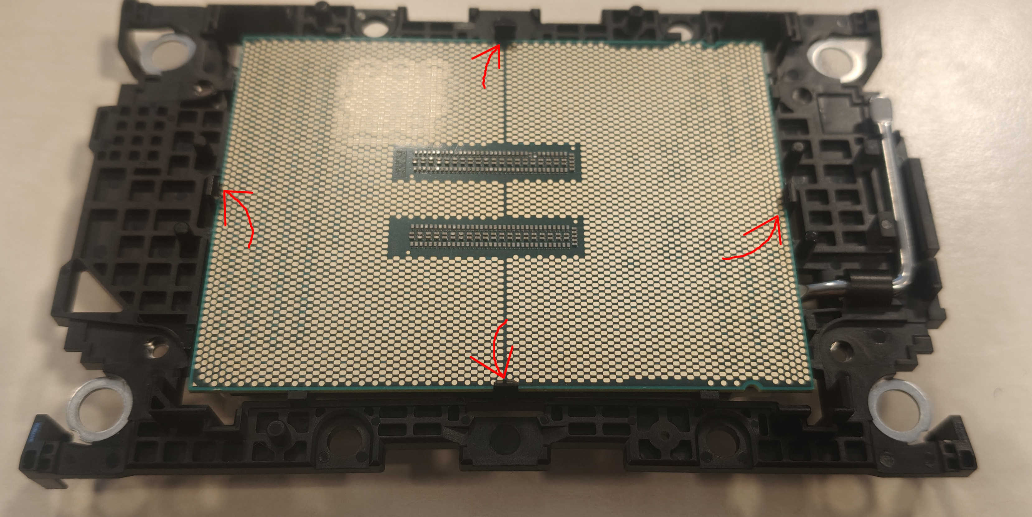
Attach the bracket to the CPU, making sure to line up the triangles and that all the clips are fully engaged.
-
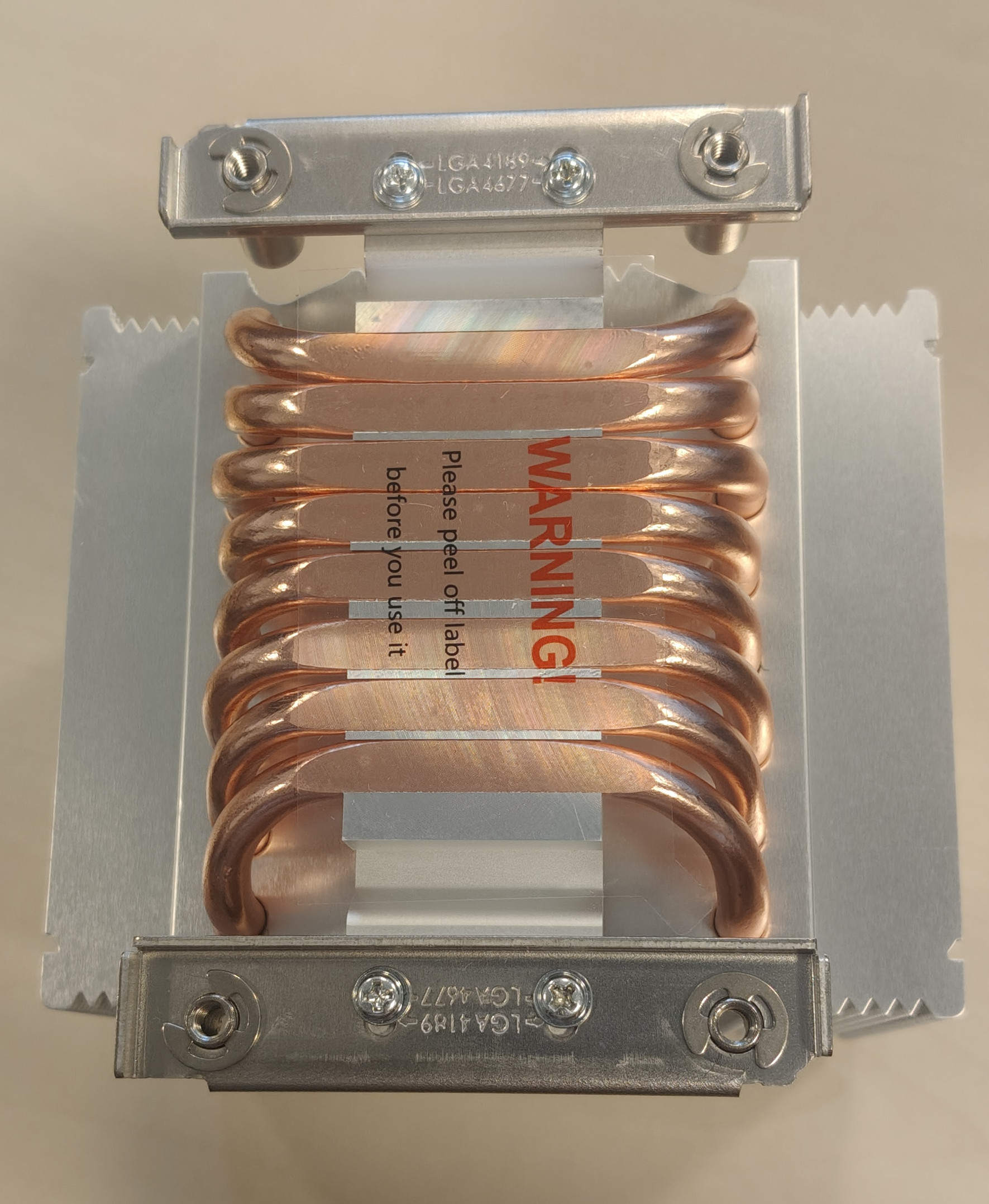
Assemble the cooler by screwing in two metal pieces on both sides of the cooler. They can be found in the accessories box marked "LGA4677". You will need to screw in the holes marked "LGA4677".
-
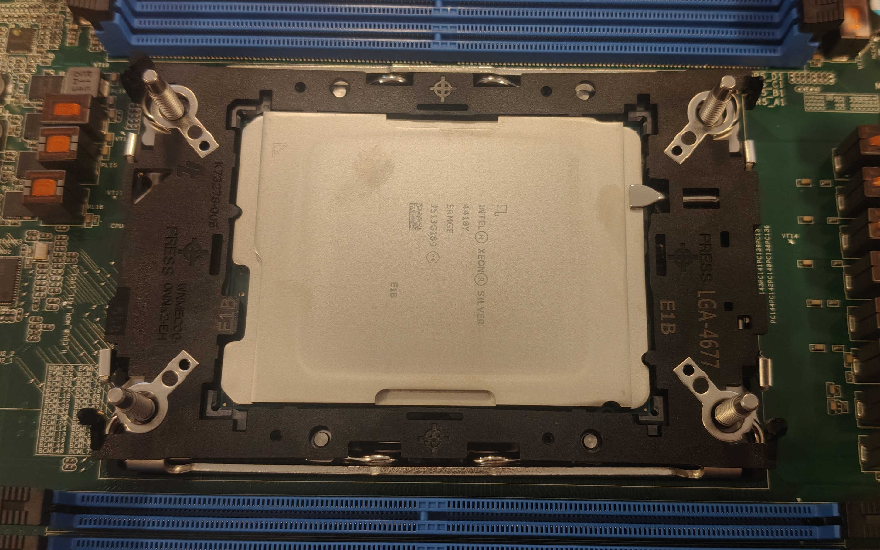
Remove the CPU socket cover from the motherboard and very carefully place the CPU into the socket, making sure to line up the triangles.
-
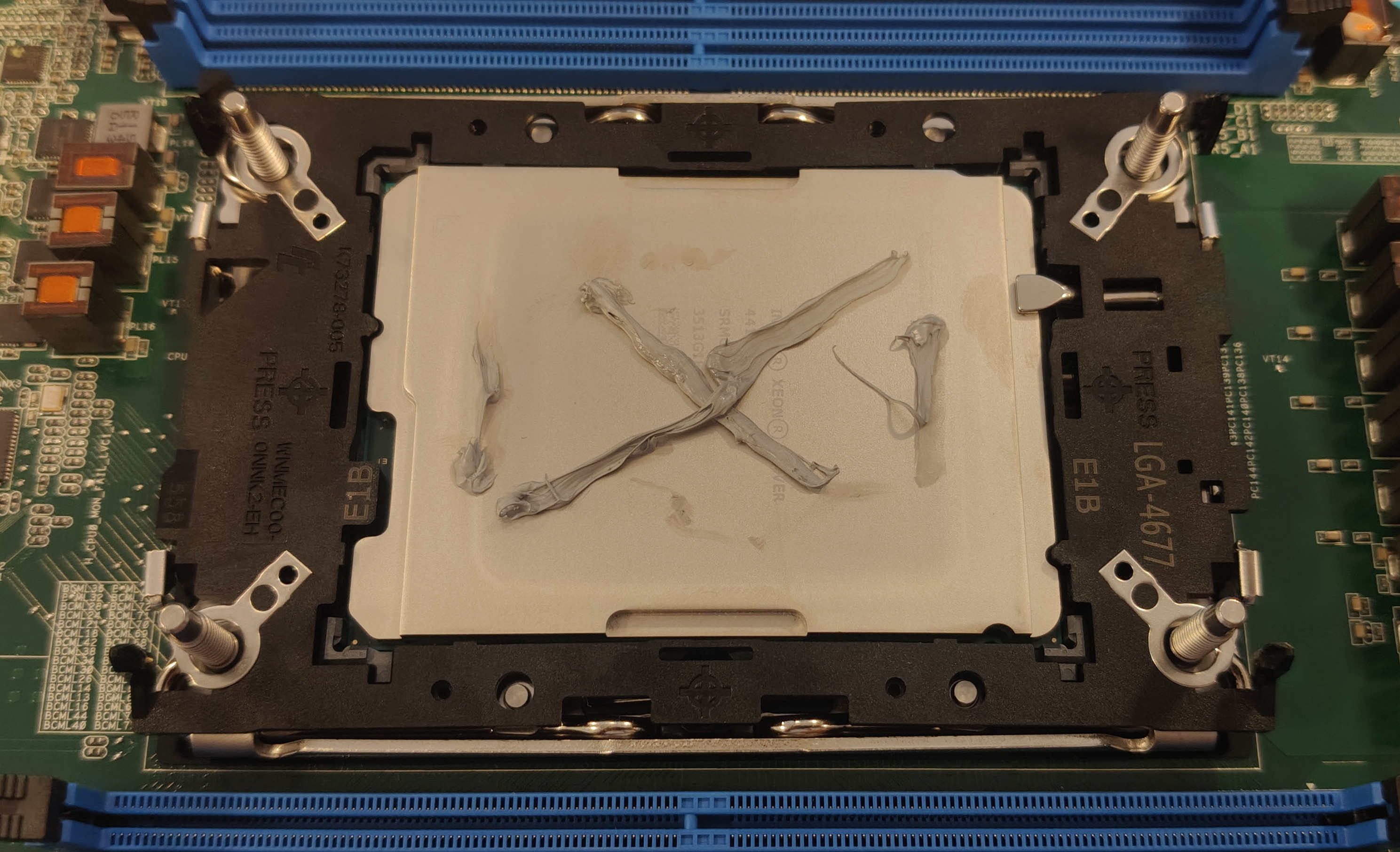
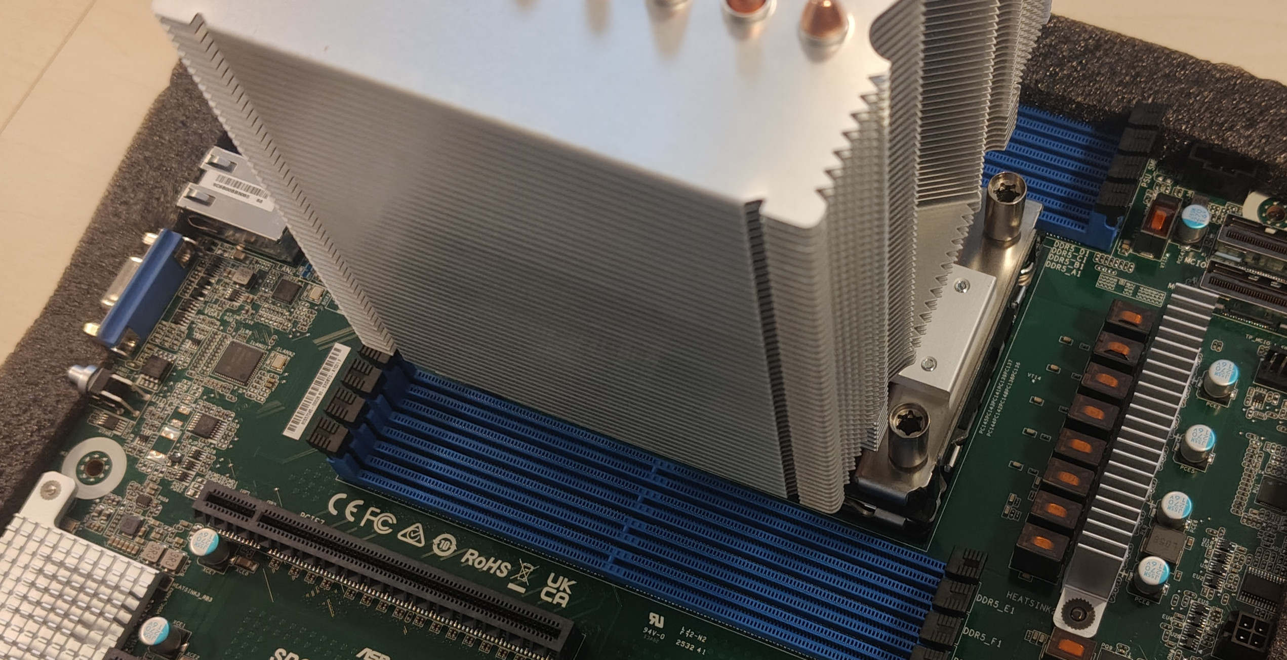
Apply thermal paste to the CPU, remove the peel from the bottom of the cooler, and place it on the CPU, ensuring the airflow arrows point in the direction of the motherboard I/O.
-
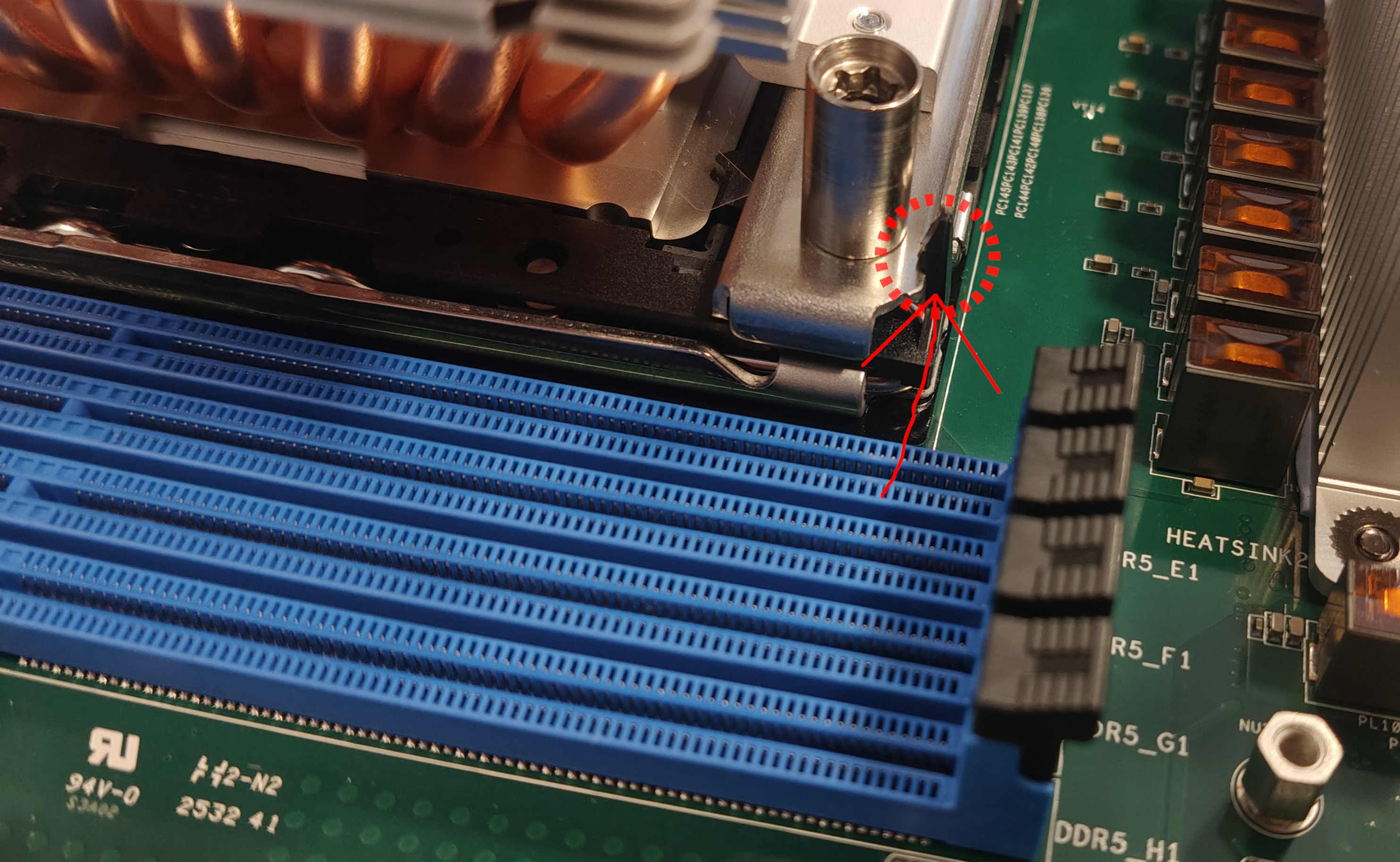
Tighten the CPU cooler using a T30 screwdriver. First, tighten the screws around halfway, then tighten the opposite corners fully. This is crucial for good contact between the CPU and the socket.
-
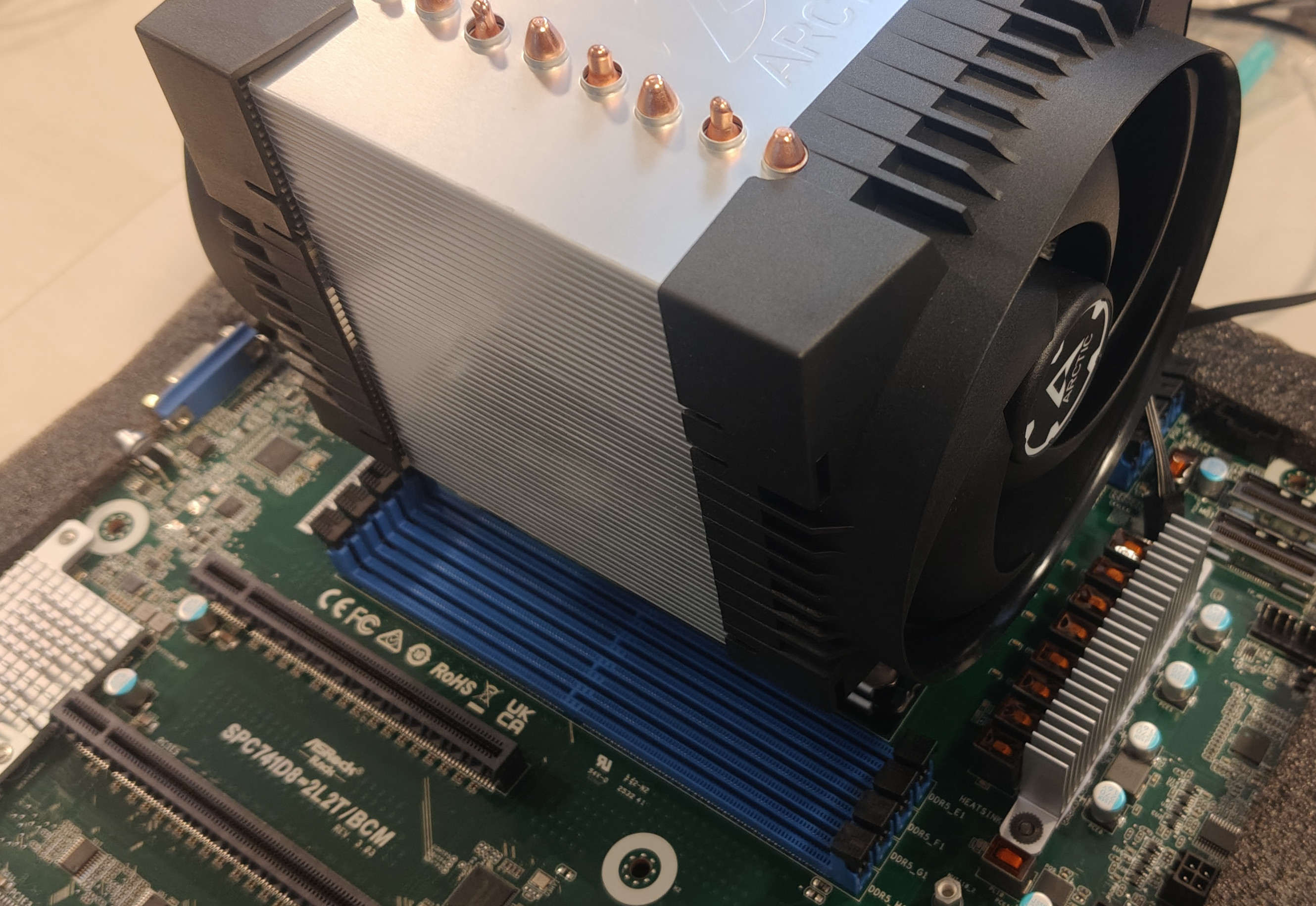
The cooler assembly can now be attached to the cooler by snapping the pieces on both sides. The fan with the Arctic logo on the front should be attached to the right side of the cooler.
-
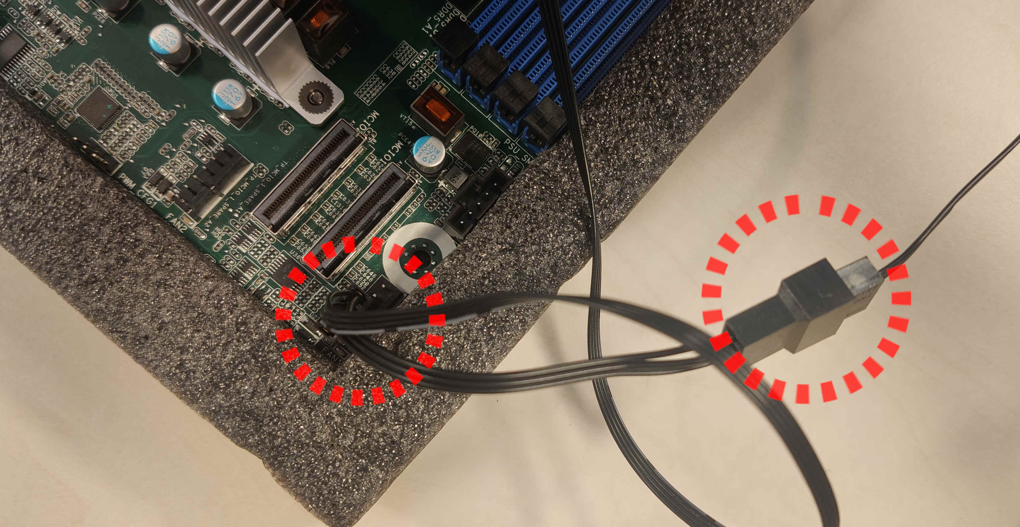
Connect the cooler fan headers by attaching them together and securing them to the motherboard in the FAN1 port.
-
Install the memory modules into the DIMM slots. To insert a single module, open the latches on both sides. Then insert the RAM and gently press downward until the latches close automatically. Install memory according to the table. If only one module is used, place it in slot A1.
DIMM Number DIMM SLOT 1 2 4 6 8 A1 V V V V V B1 V V C1 V V D1 V V E1 V V F1 V V G1 V V V V H1 V V 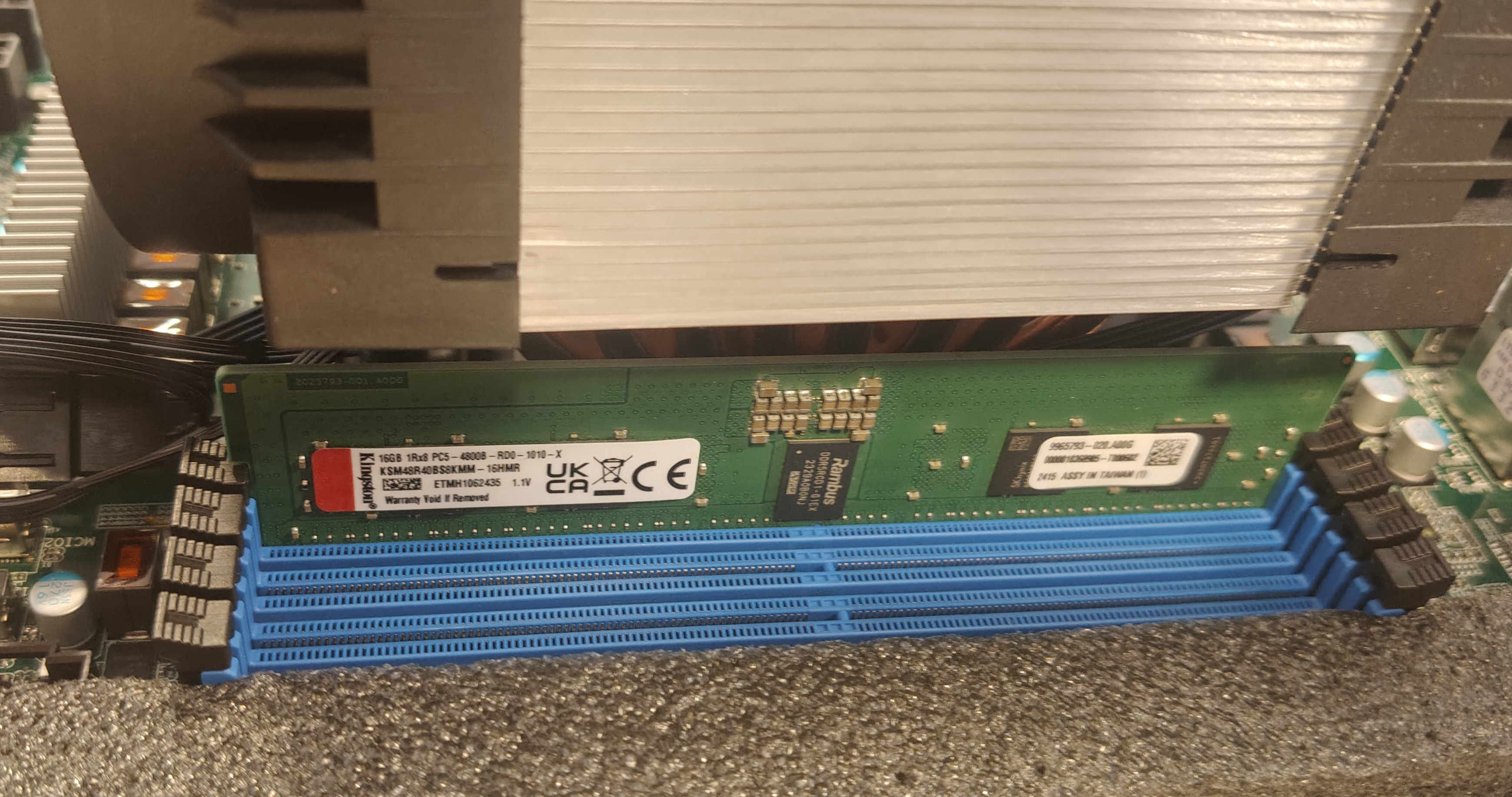
-
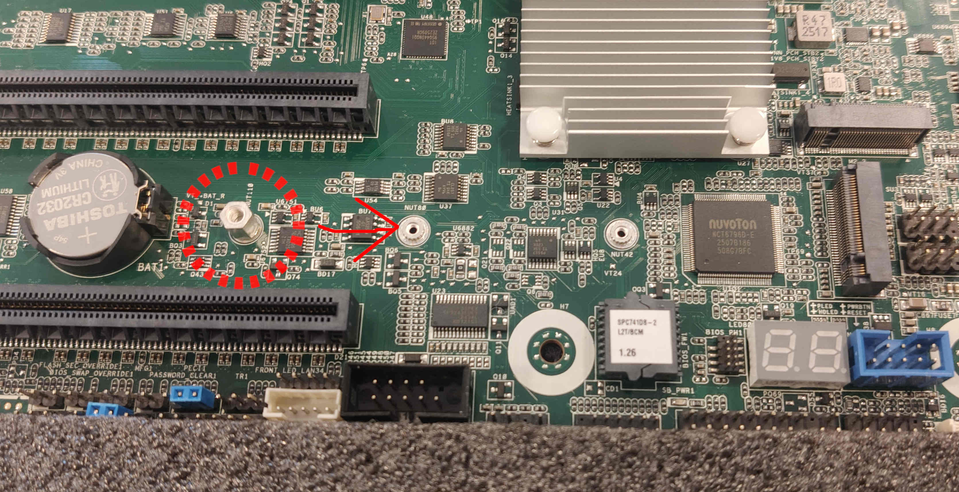
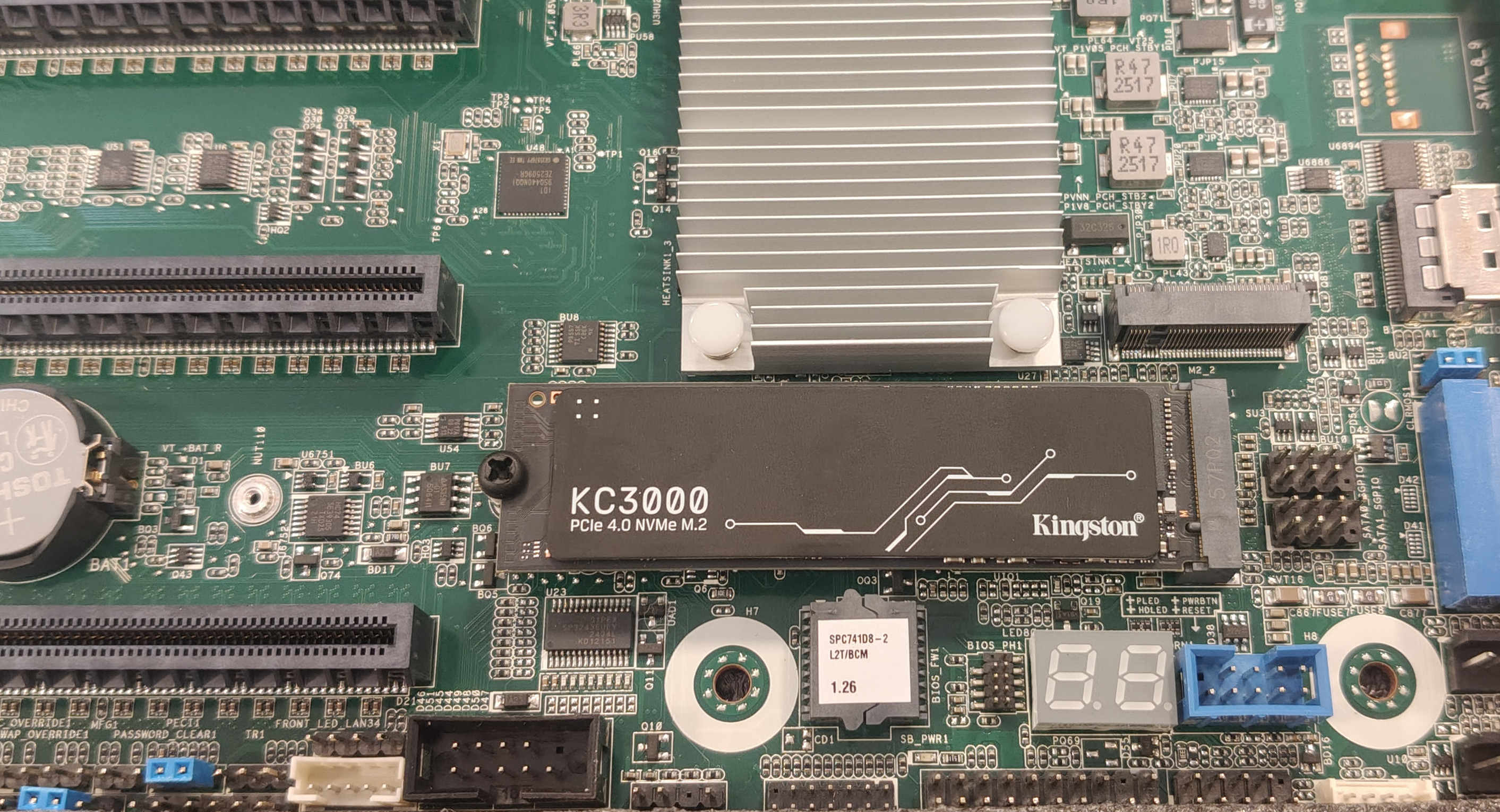
Using pliers, unscrew and screw back the SSD standoff one hole closer to the M.2 slot. Install the M.2 solid-state drive (SSD) into the M.2 slot and tighten the screw holding it. (You may need additional M3 screw for that)
-
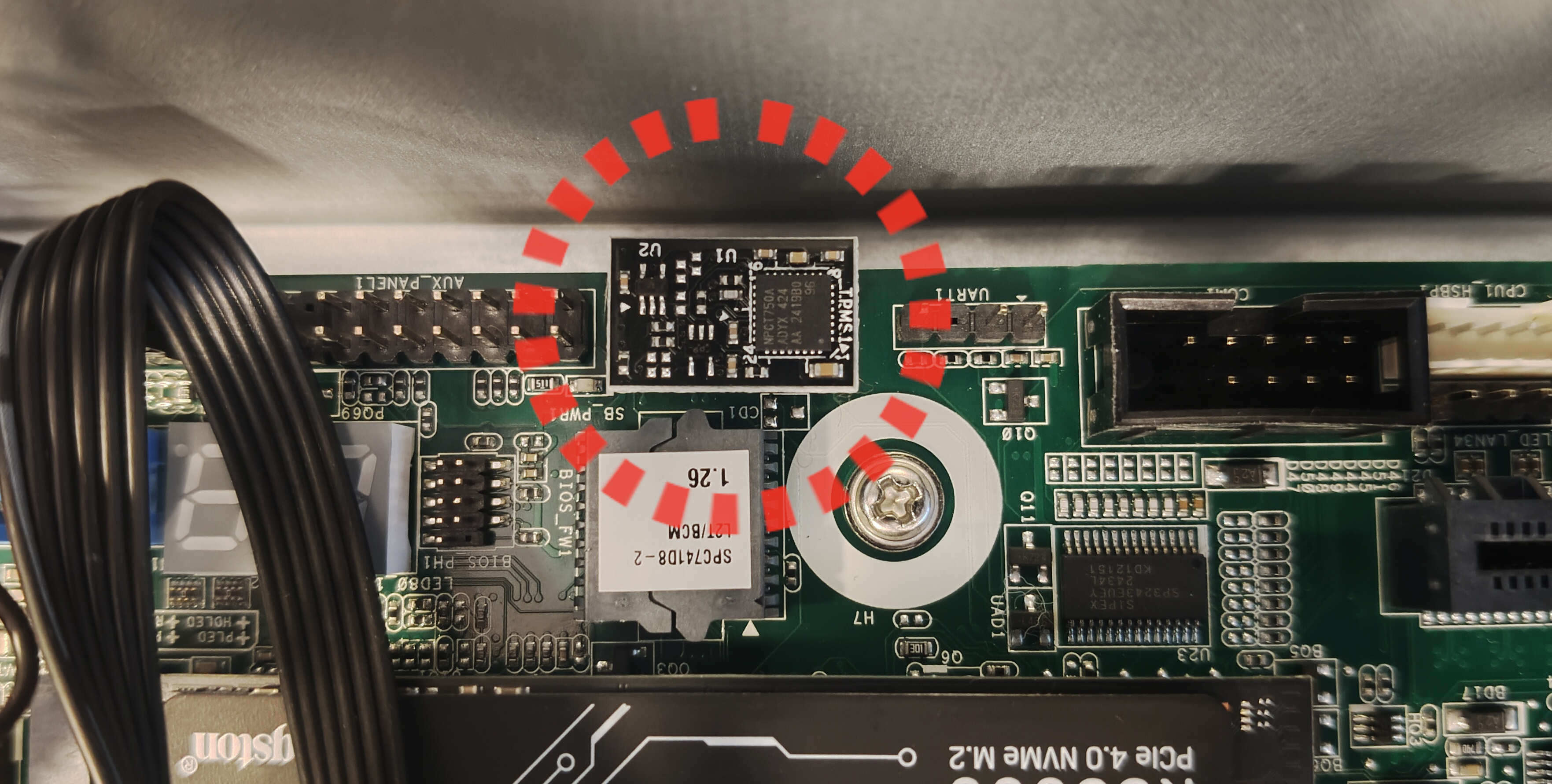
Install the TPM module in the slot marked "TPM_BIOS_PH1"
-
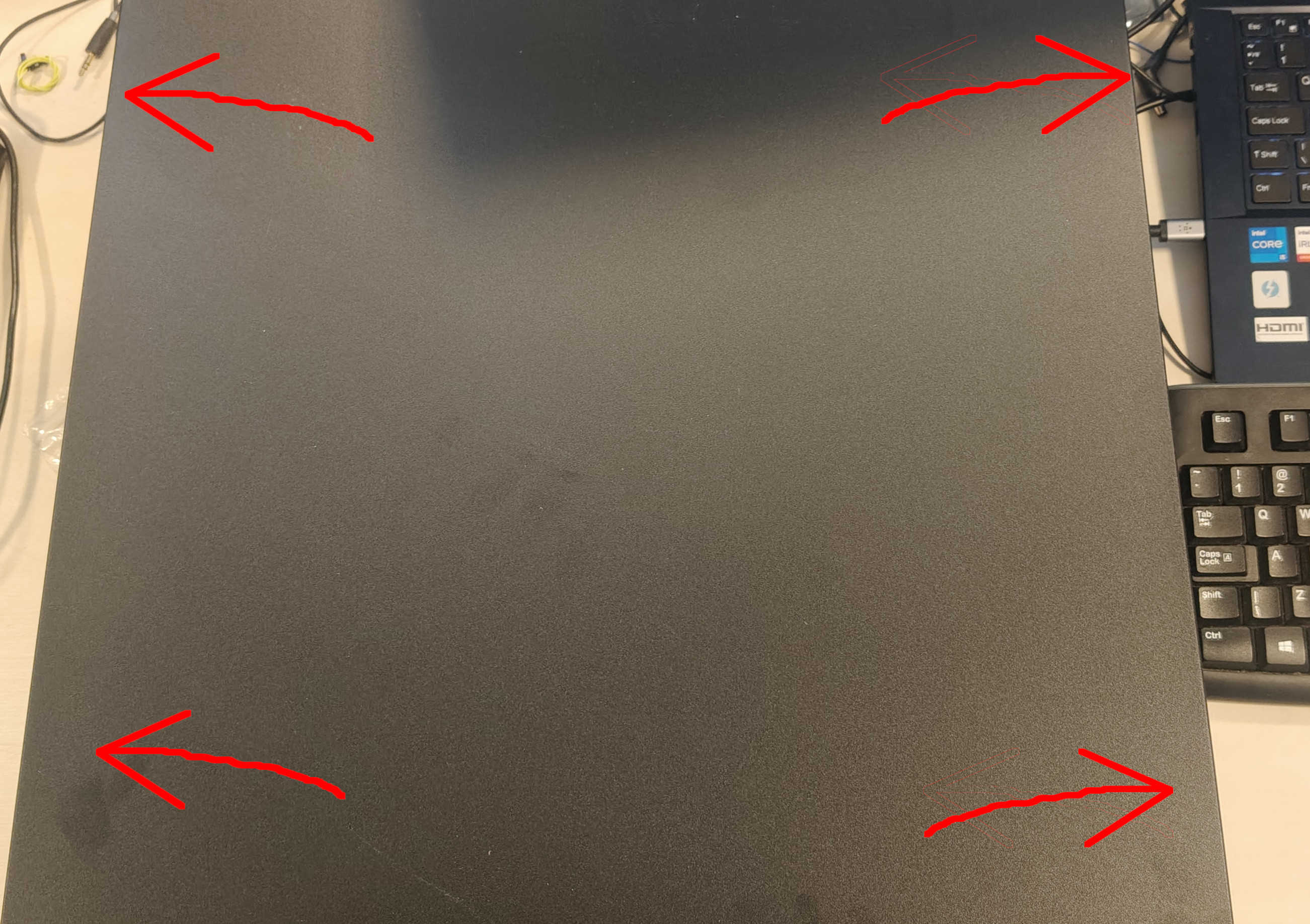
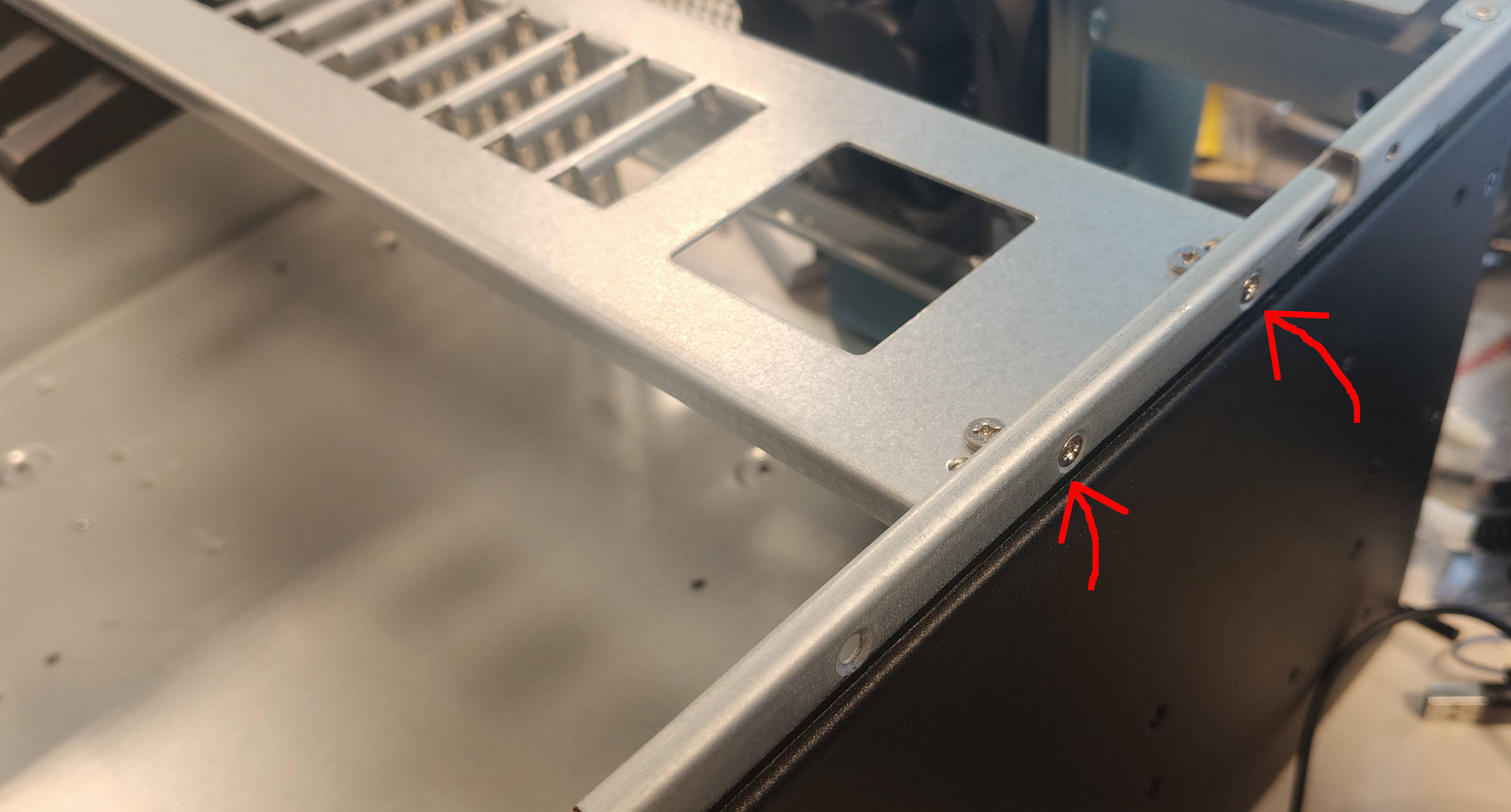
Open the chassis by removing four screws from both sides of the top panel and remove the metal PCIe cards holder by unscrewing four screws on the left and right sides (not the top). This piece will not be reinstalled in the case.
-
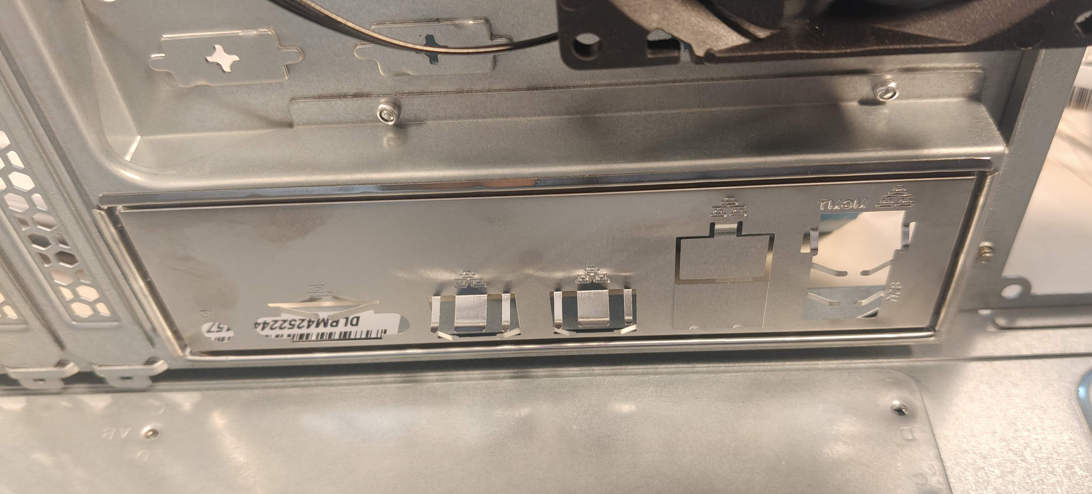
Install the IO shield by inserting it from inside the enclosure and pressing it lightly.
-
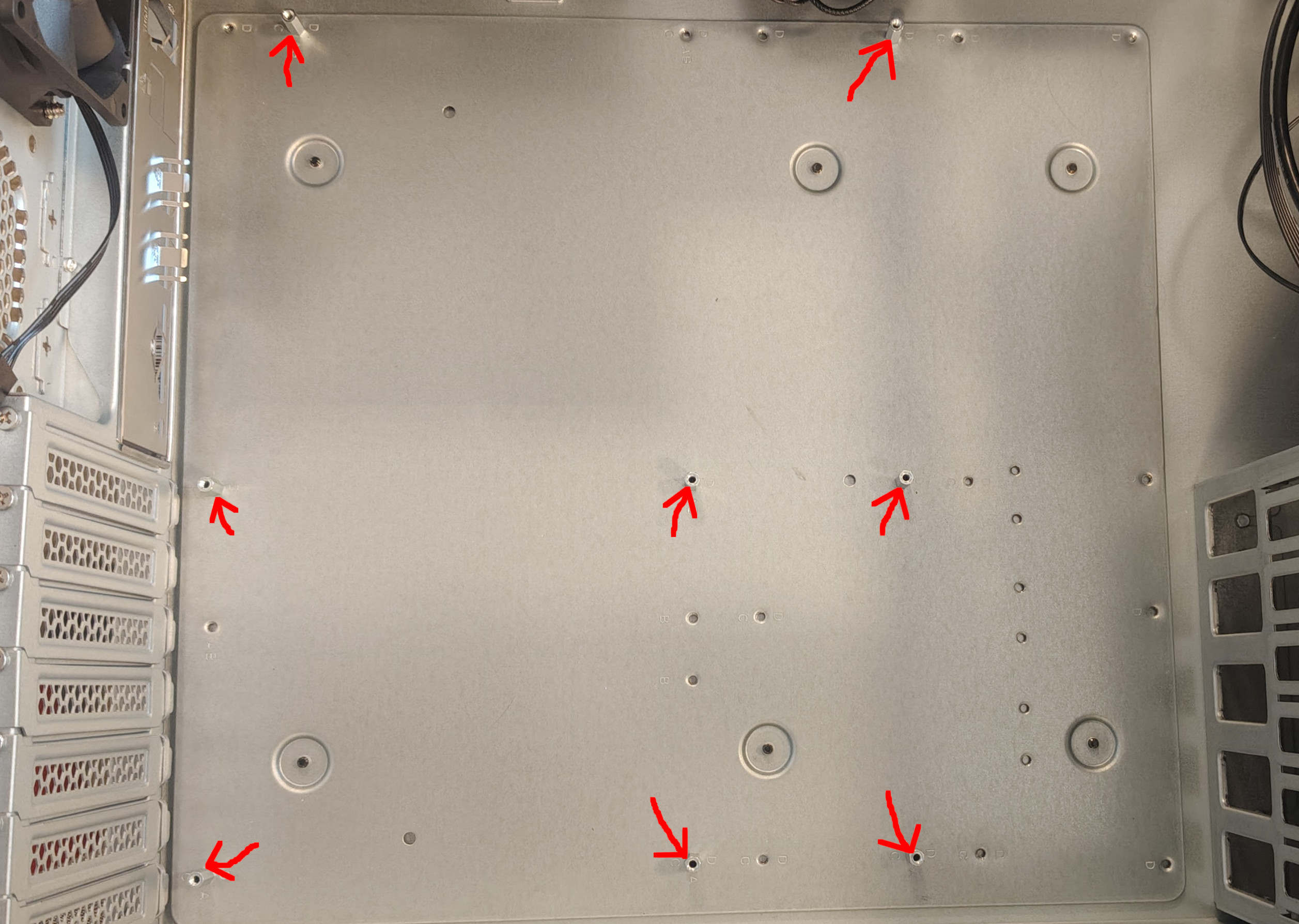
Make sure there are standoffs installed in all the correct spots, as shown in the picture.
-
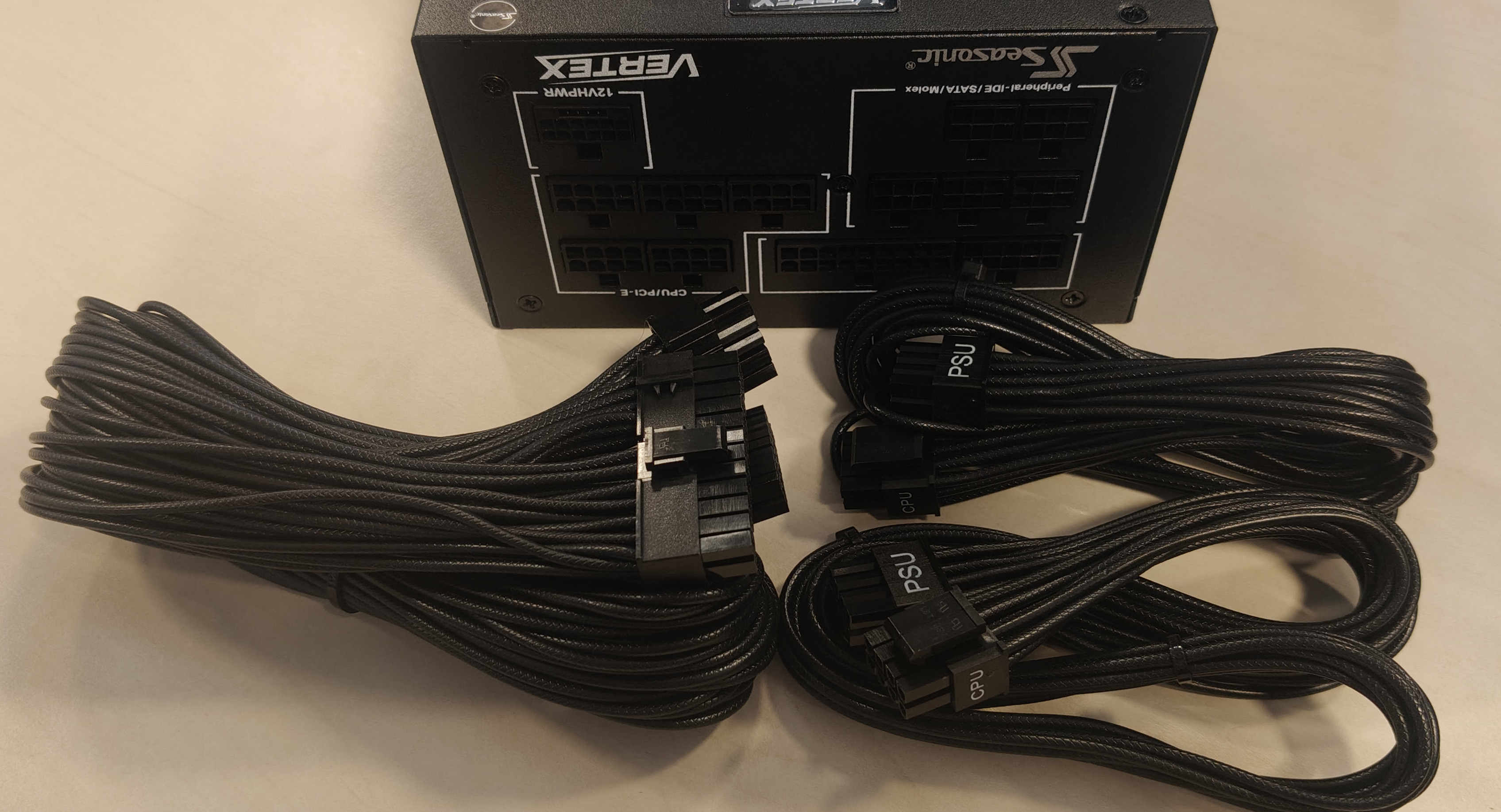
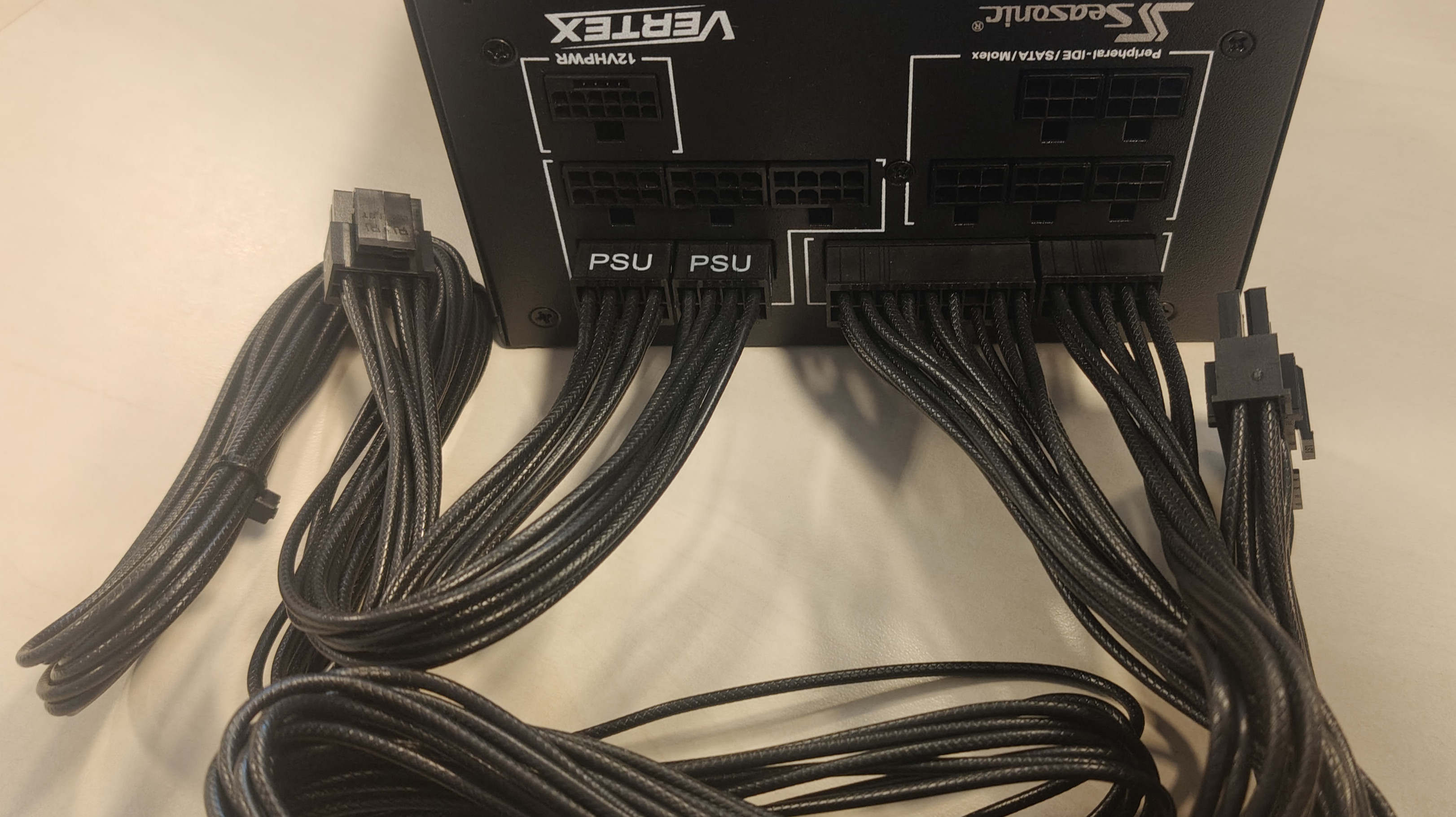
Before installing the power supply, locate and plug in the two CPU power cables and one 24-pin connector.
-
Install the PSU in the case by placing it in its slot on the right side of the case and securing it with all four screws at the back.
-
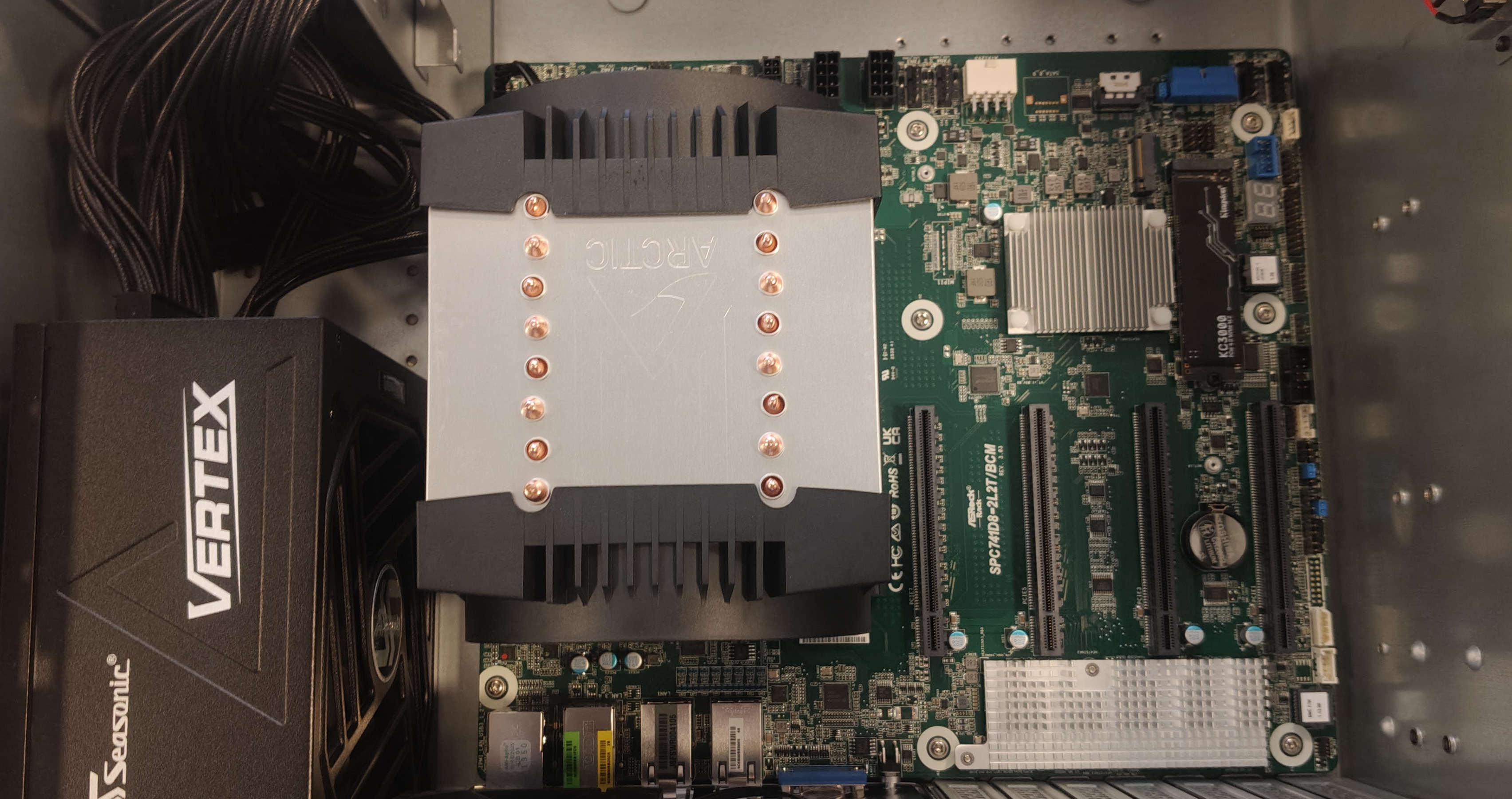
Place the motherboard into the case and fasten it with screws in the marked spots.
-
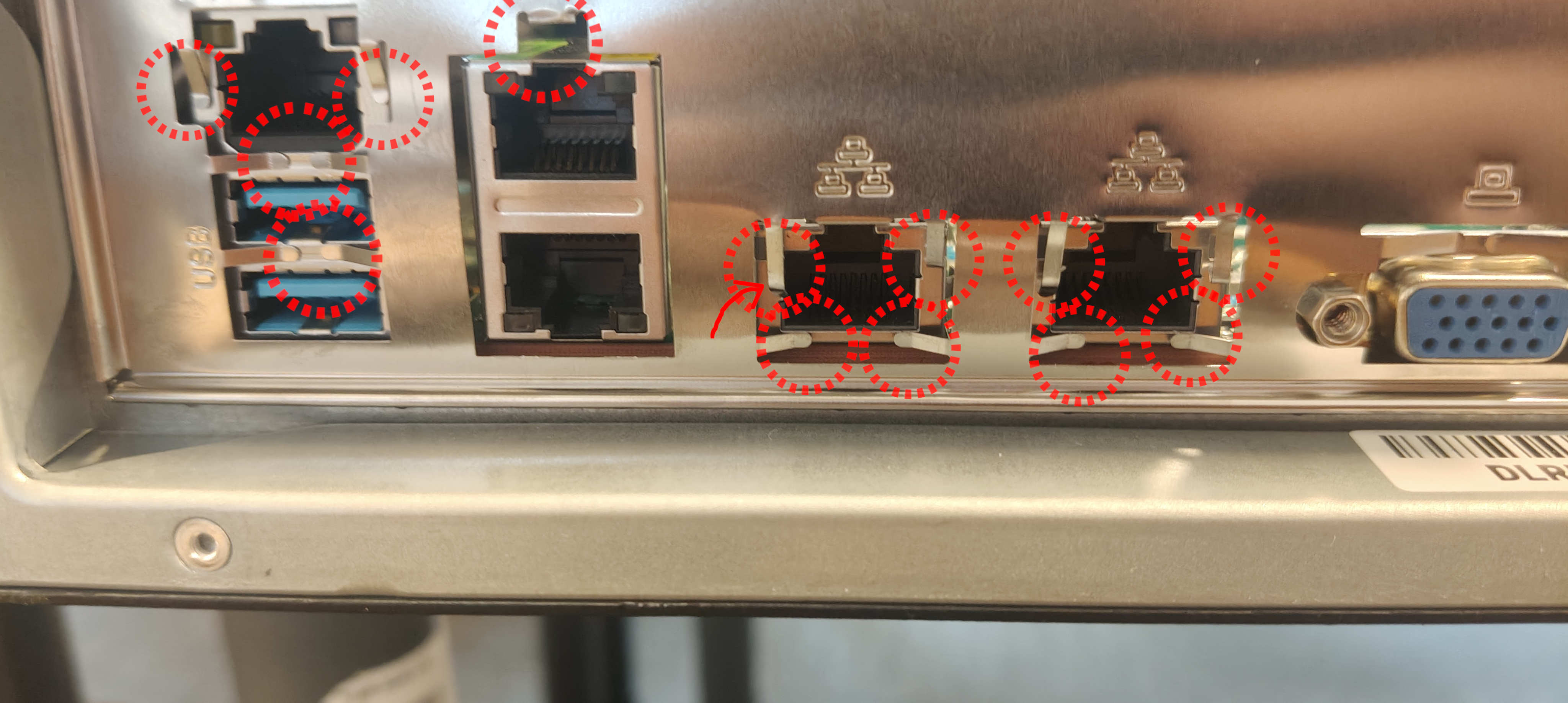
Ensure the IO shield covers for RJ-45 ports are properly trimmed, and that no metal tabs interfere with any ports.
-
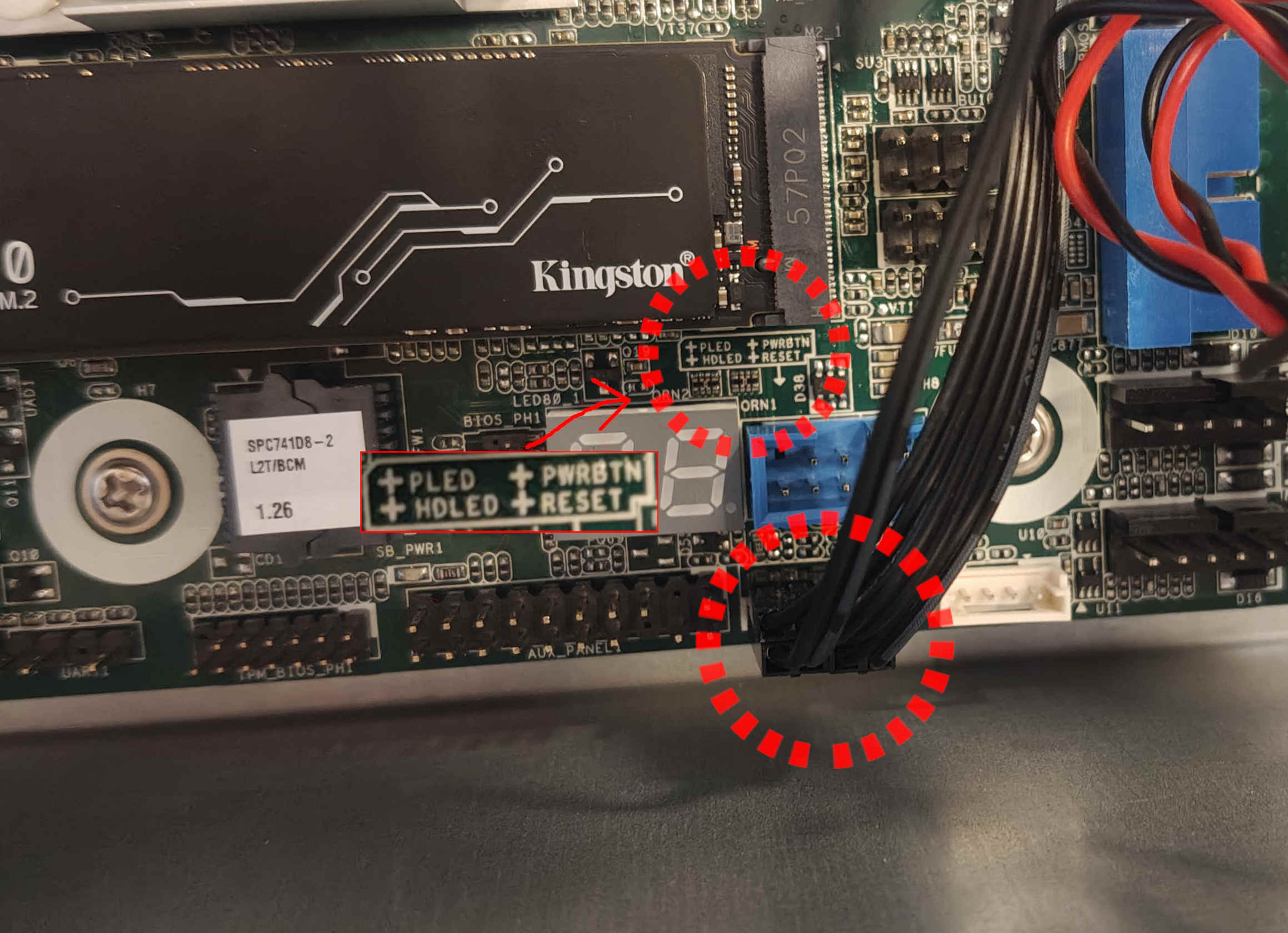
Connect the front-panel cables to the appropriately marked spots.
-
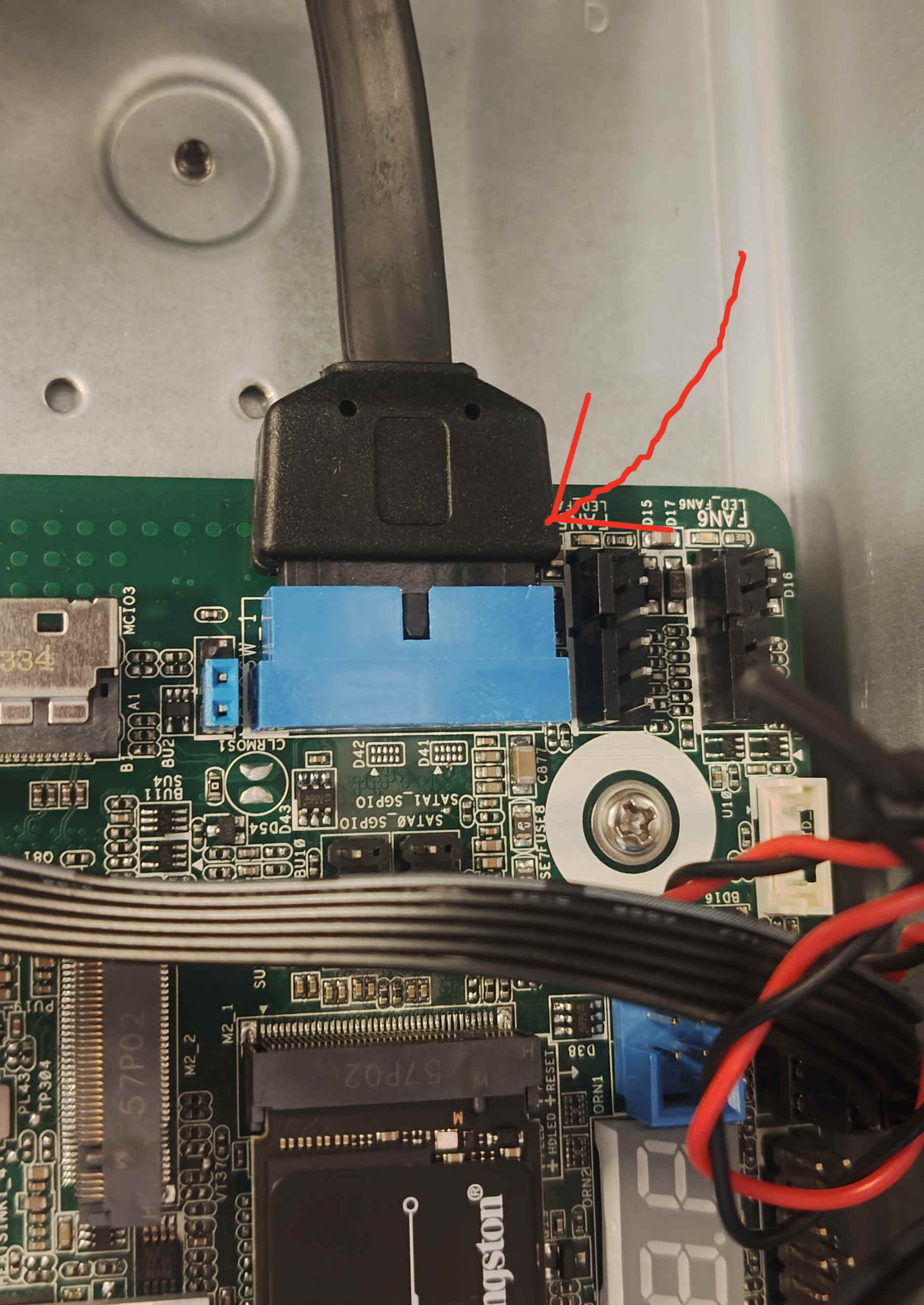
Connect the USB 3.0 cable to the port marked "USB3_3_4".
-
Connect the front fan to the "FAN4" header on the motherboard. To connect the rear fan, an extender will be needed to connect it to the "FAN3" connector.
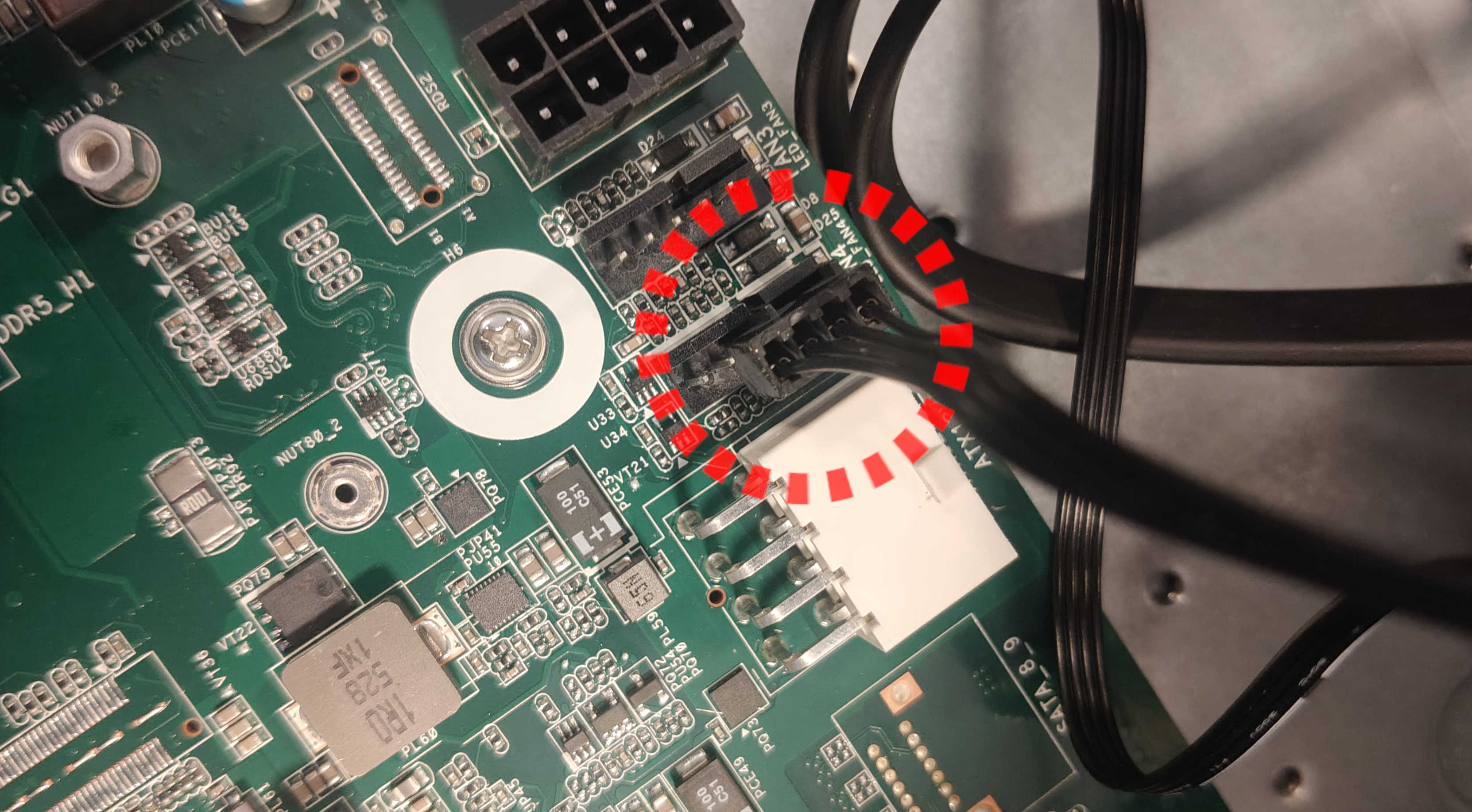
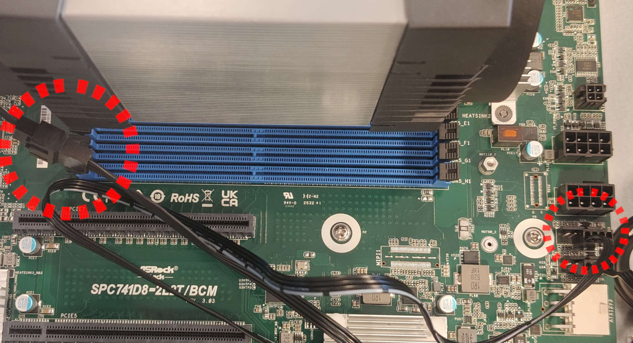
-
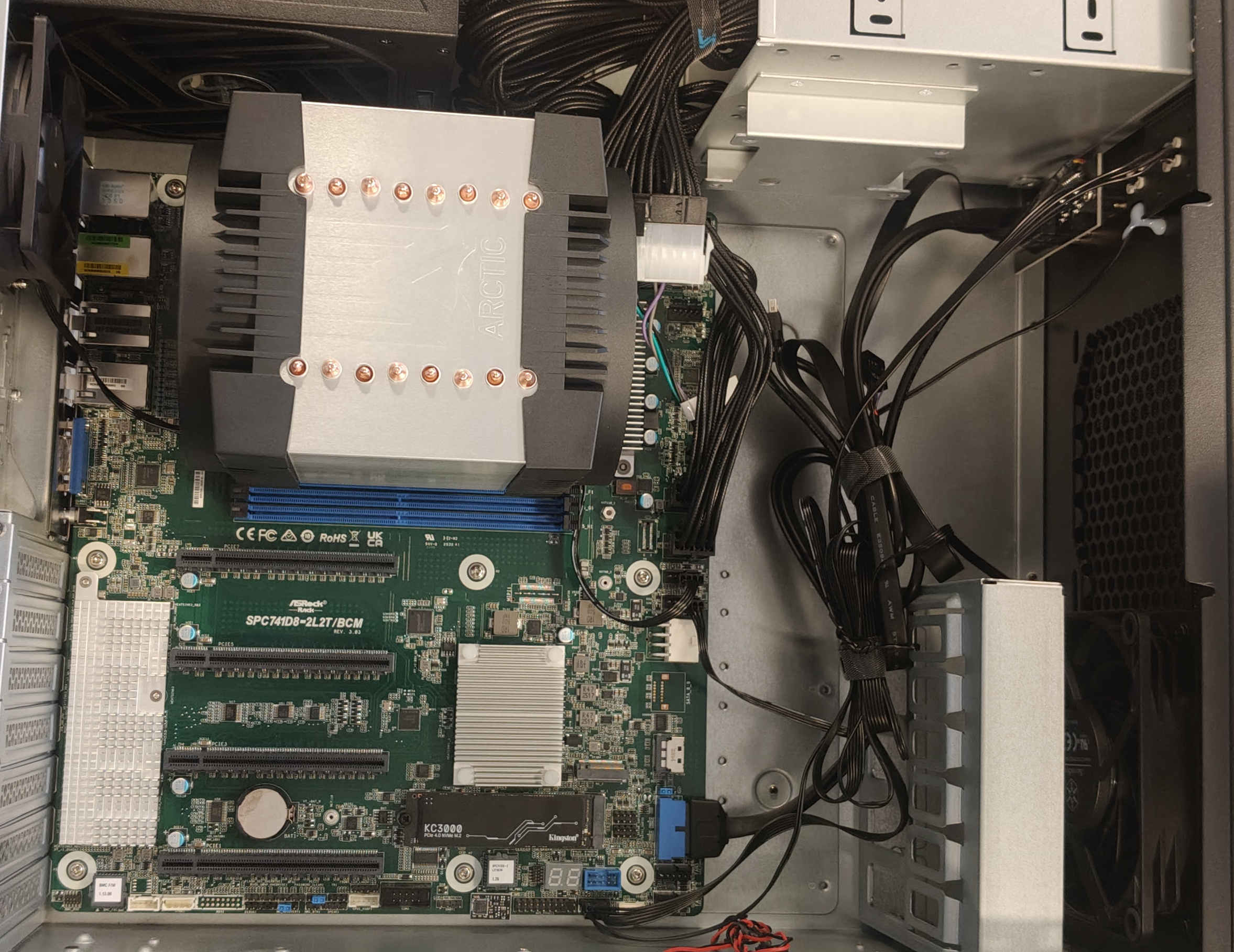
Connect the power supply to the motherboard as shown in the provided images. For a 24-pin connector, an adapter provided with the motherboard will be needed.
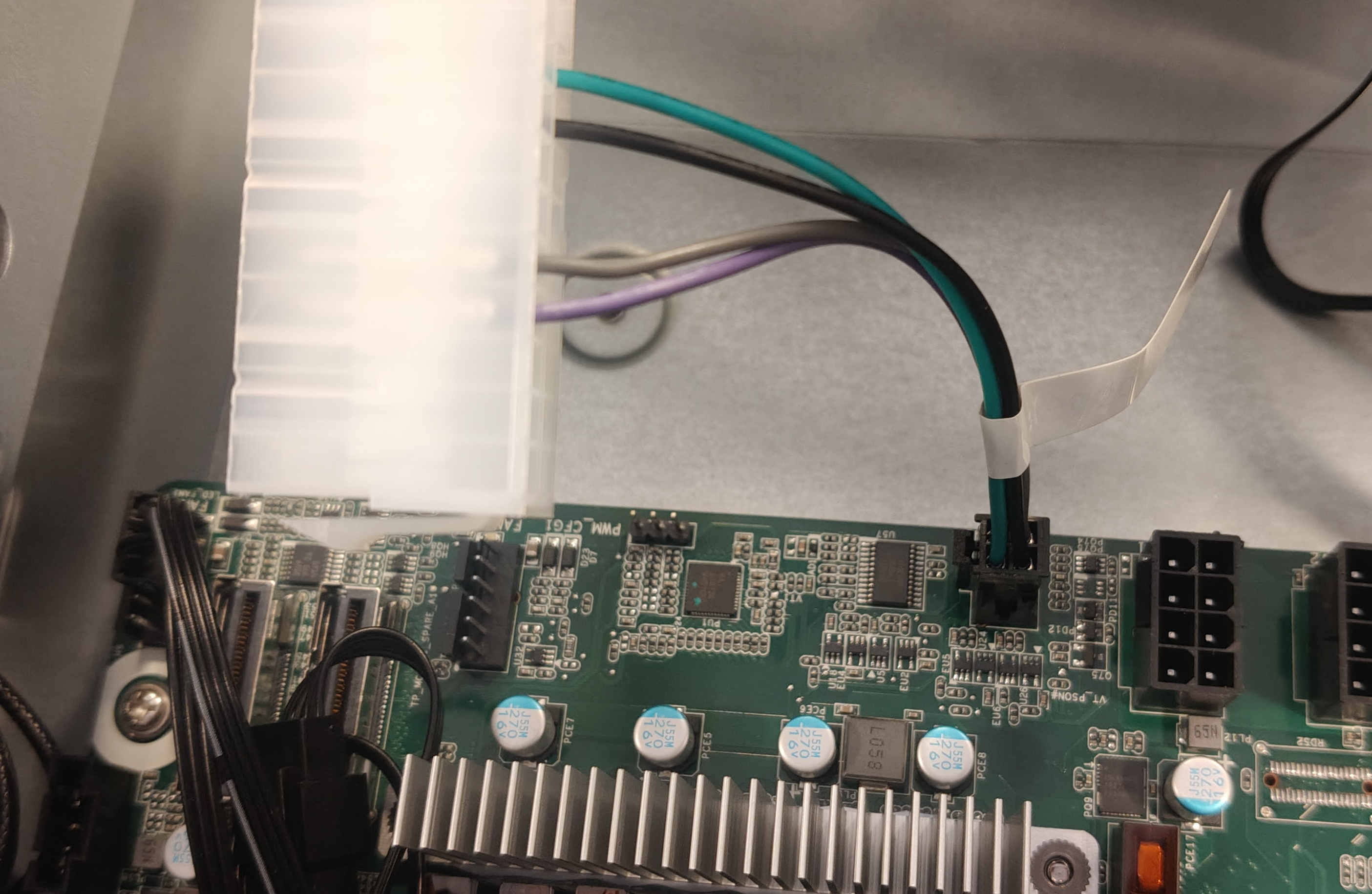
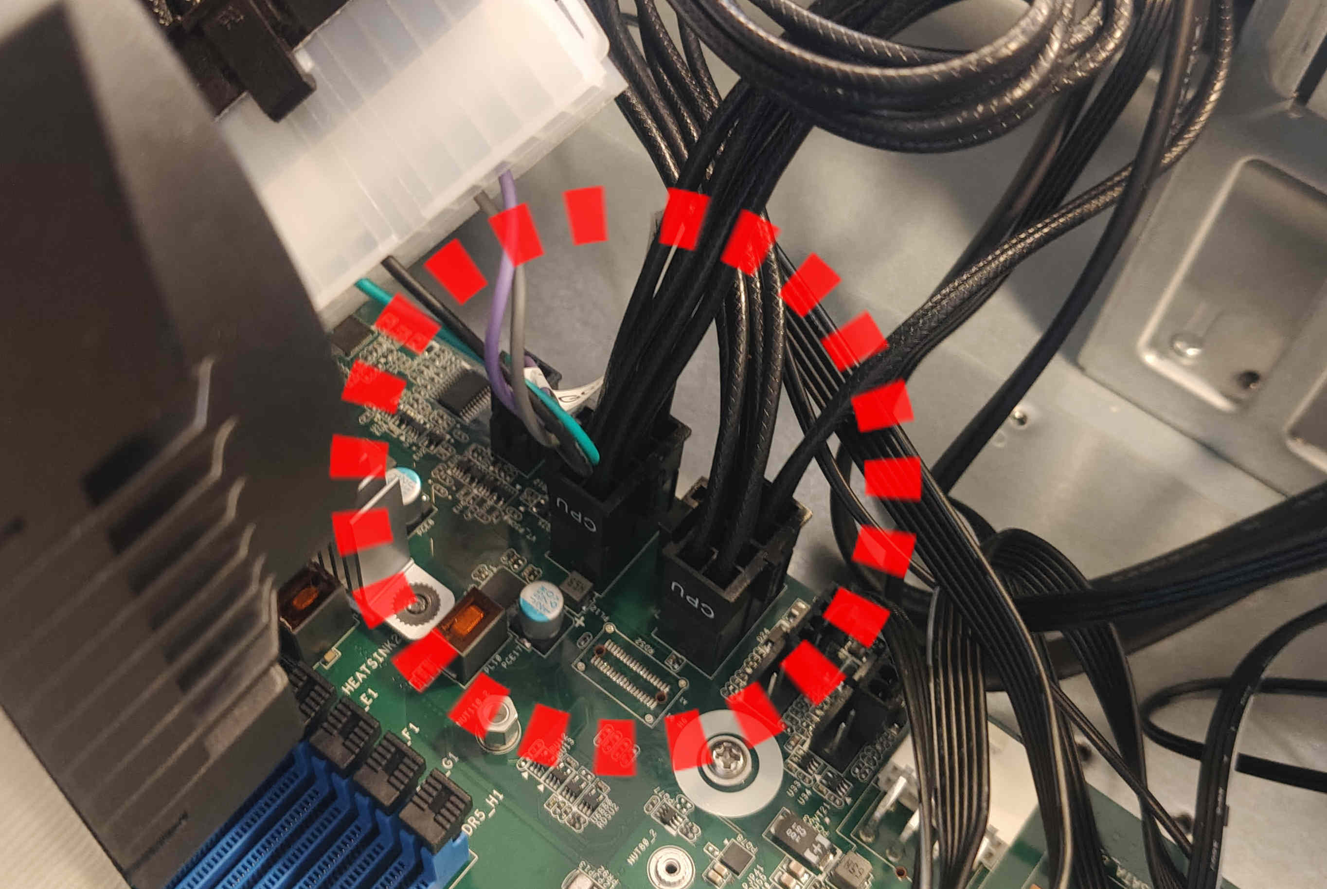
-
Bundle cables so they do not interfere with fans or other components.
-
Close the case by reinstalling all four screws.
-
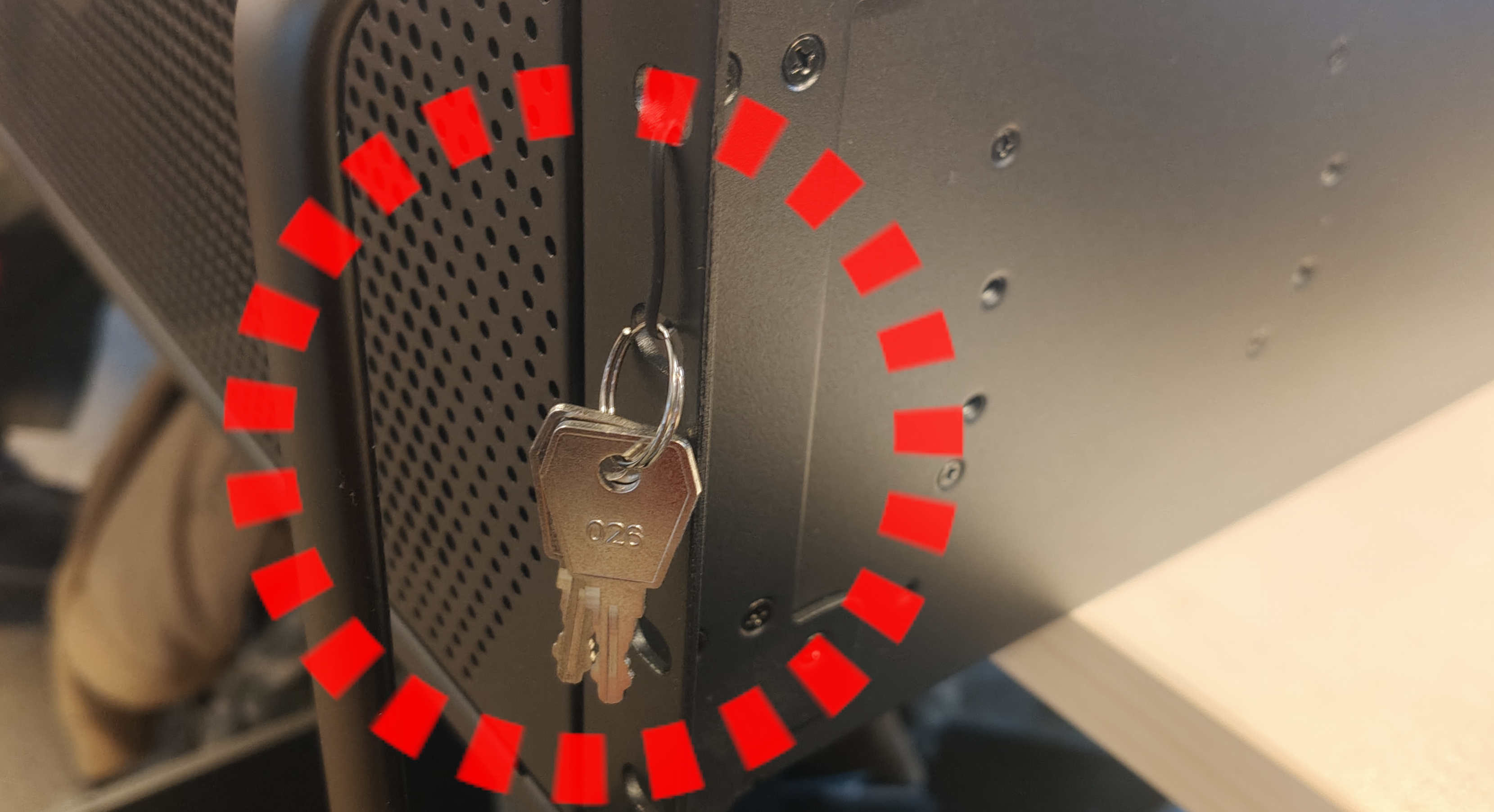
Attach case keys to the front of the case to prevent loss or damage during shipping.
Stock Firmware verification
Once the platform gets assembled, it is crucial to verify its functionality before attempting to flash Dasharo firmware. This is to exclude the possibility of the platform not booting due to bad hardware configuration.
Here's a list of steps that need to be performed:
-
Download the latest DTS version (pre-release (
rc) included) from releases and flash the image to the flash drive. For non-technical users, it is recommended to use Etcher to flash the image onto the flash drive. -
Connect the device to the mains power.
- Open the front panel using the attached key.
- Plug the previously prepared flash drive into one of the available USB ports.
- Power on the device with the button located on the front panel.
- Make the platform boot from the flash drive.
- Once DTS boots, run the HCL report with an option to send the logs to 3mdeb.
- Power off the device.
Flashing Dasharo Firmware
The Dasharo firmware is flashed externally by removing the BIOS memory chip from its socket and flashing it in a dedicated SOIC-16 adapter connected to a CH341A (v1.7) programmer. The full step-by-step procedure — removing the chip, setting up the programmer, flashing, and putting the chip back — is described in the recovery guide.
Obtaining the firmware
-
Obtain the newest firmware for the platform. Log in to Minio, and go to the
dasharo-asrock-spc741d8-uefi/SPC741D8directory. The directory stores all available firmware versions. Go to the directory containing the newest available firmware version and download the two files:- the firmware binary file with
.romextension. - the control checksum file with extension
.rom.sha256.
- the firmware binary file with
-
In the terminal, go to the directory where the files have been downloaded.
-
Execute the following command to verify whether the checksums match.
Command:
sha256sum asrock_spc741d8_*.rom && cat asrock_spc741d8_*.rom.sha256The output of the command shall be as follows.
Example log:
λ sha256sum asrock_spc741d8_*.rom && cat asrock_spc741d8_*.rom.sha256
85e76fc57b5673c93aec6eb9e46ba00237f13636d62697506707971a28aa7a92  asrock_spc741d8_v0.9.0.rom
85e76fc57b5673c93aec6eb9e46ba00237f13636d62697506707971a28aa7a92  asrock_spc741d8_v0.9.0.rom
Note: The checksums shown in the example above are just an example.
The command will print out the checksum calculated locally and the master checksum afterwards. If the checksums match, one can proceed.
Flashing and verification
- Flash the firmware onto the BIOS memory chip and reinstall it into the
socket by following the
recovery guide. Use the
firmware
.romfile downloaded and verified above as the binary to flash. NOTE THAT THIS ACTION IS DESTRUCTIVE. THE DEFAULT FIRMWARE WILL BE ERASED! -
Supply the power to the platform, and follow the procedure from the "Stock Firmware Verification".
The platform will take some time to boot for the first time, and it might switch on and off multiple times during the procedure.
When DTS is booted, verify that the proper firmware version has been flashed.
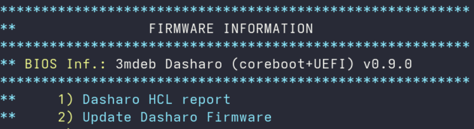
The picture above showcases the DTS menu. The firmware information and version shall be listed as in the image above. Note that the version shown in the picture is just an example.
-
Stick the holographic sticker on top of the socket. After the platform has been verified to be working and proper firmware has been installed, the socket needs to be sealed.
Remove the leftovers from the original paper sticker with isopropyl alcohol and Q-tips (cotton buds). When the surface is dry, stick the new 3mdeb holographic sticker parallel to the bottom edge of the motherboard. Make sure the text orientation matches the text on the silkscreen (it's a nice quality touch).
When all steps were performed, the platform is ready to be backed up and shipped.
Useful content
- Building manual - documentation contains information on how to build Dasharo compatible with ASRock SPC741D8.
- Board Manual - documentation contains detailed information about the motherboard and its operations.
- CPU Cooler Manual - documentation contains information on how to properly assemble the CPU Cooler and mount the CPU to it.