Laboratory stand dedicated to MGigabyte MZ33-AR1 platform assembly guide
Introduction
This document describes platform-specific details for assembling an Gigabyte MZ33-AR1 testing stand. Use this document as reference while going through Generic Testing Stand Setup
Prerequisites
The below table contains information about all elements which are needed to create the testing stand.
- Gigabyte MZ33-AR1 platform
- RTE v1.1.0
- Sonoff S20 type E
- 9x standard female-female connection wire 2.54 mm raster
- Pomona SOIC8 clip
- DB9 null modem cable
- Board manual
Connections
The following sections describe how to enable all of the following features:
- serial connection to the platform,
- controlling power supply,
- enabling basic power actions with the platform (power off/power on/reset),
- external flashing with the RTE,
Serial connection
Connect the DB9 null moden cable to the RTE DB9 connector and DB9 connector on the rear panel of Gigabyte MZ33-AR1.
Power supply controlling
Connect the PSU power cord to Sonoff.
Basic power operations enabling
Connect the RTE J11 header to the platform JFP1 header as described in the table:
| RTE | Gigabyte MZ33-AR1 FP_1 |
|---|---|
| J11 pin 9 | FP_1 pin 11 (PWR_ON) |
| J11 pin 8 | FP_1 pin 15 (RST) |
| J15 pin 1 (GND) | FP_1 pin 13 (GND) |
| J10 pin 1 | FP_1 pin 5 (PWR LED-) |
The
Power LED-has inverted polarity. When board is running, its state is low. When board is off, then the state is high.Power LED+is always high when PSU is on.
External flashing enabling
-
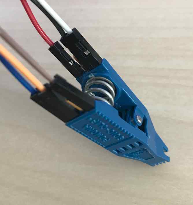
Connect the wire cables to the Pomona clip.
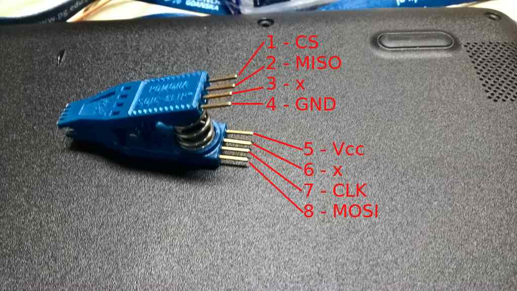
-
Connect the Pomona clip to the SPI header on RTE.
SPI header Pomona clip Vcc pin 5 (Vcc) GND pin 4 (GND) CS pin 1 (CS) SCLK pin 7 (CLK) MISO pin 2 (MISO) MOSI pin 8 (MOSI) 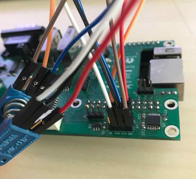
-
Clip on the BIOS chip on the board:

Complete Setup
After preparing all of the connections also three activities should be performed to enable all of the test stand features:
-
Connect Sonoff to the mains:

-
Connect the RTE to the Internet by using the Ethernet cable.
- Connect the RTE to the mains by using the microUSB 5 V/2 A power supply.
Complete setup should looks as follows:


Theory of operation
The following sections describe how to use all of the enabled features:
- serial connection to the platform,
- controlling power supply,
- enabling basic power actions with the platform (power off/power on/reset),
- external flashing with the RTE,
- device power status readout.
Serial connection
The method of setting and using serial connection is described in the Serial connection guide.
Power supply controlling
Power supply controlling (in this case: controlling the state of Sonoff) should be performed with osfv_cli.
To perform basic power operations use the commands described below:
-
Turn on the power supply:
osfv_cli sonoff --sonoff_ip <sonoff_ip_address> on -
Turn off the power supply:
osfv_cli sonoff --sonoff_ip <sonoff_ip_address> off
Basic power operations
Basic power operations should be performed based on the osfv_cli. To perform basic power operations use the commands described below:
-
Turn on the platform:
osfv_cli rte --rte_ip <rte_ip_address> pwr on -
Turn off the platform:
osfv_cli rte --rte_ip <rte_ip_address> pwr off -
Reset the platform:
osfv_cli rte --rte_ip <rte_ip_address> pwr reset
Note, that in order for the above commands to work properly, the platform should be powered up: both Sonoff and the power supply must be turned on.
External flashing
The external flashing procedure should be performed using OSFV cli.
For external flashing hardware connection please refer to the board's recovery section (setup with RTE).
Ethernet
The board IPMI Ethernet (5) as well as first Ethernet port (4) for host should be connected to the network.
